Installation
Inspect the UPS for damages. Follow these location guidelines:
-
Place the UPS on a flat, clean surface and away from vibration, dust, humidity, high temperature, flammable liquids, gases, and corrosive and conductive contaminants.
-
Install the UPS indoors in a clean environment, away from windows and doors.
-
The UPS operates normally at an altitude of 3,000 m (1.86 miles) or lower for the UPS to operate normally with a full load.
Rack-mount installation
-
Install the included rack ears on the UPS.
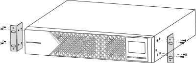
-
Mount it in the rack using standard rack screws.
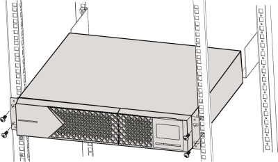
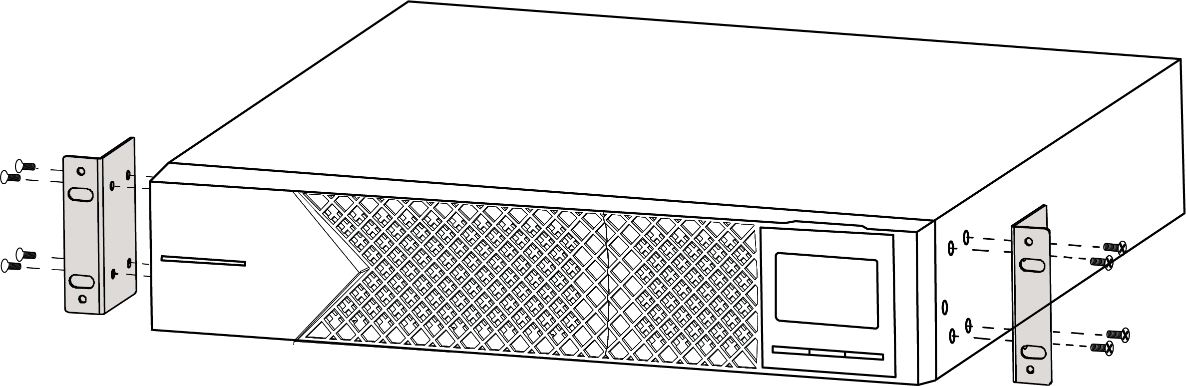
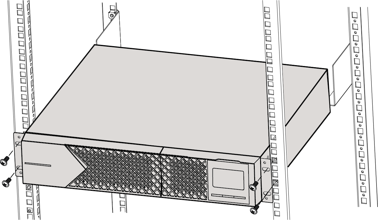
Pro Tip: Mount the UPS at the bottom of the rack so it does not tip over.
External Battery Pack compatiblity
The WB-OVRC-OLUPS-1000-1 is only compatible with the External Battery Pack (WB-UPS-EBP-18AH24V).
The WB-OVRC-OLUPS-1500-1 and WB-OVRC-OLUPS-2000-1 are only compatible with the External Battery Pack (WB‑UPS‑EBP‑18AH48V).
External Battery Pack installation
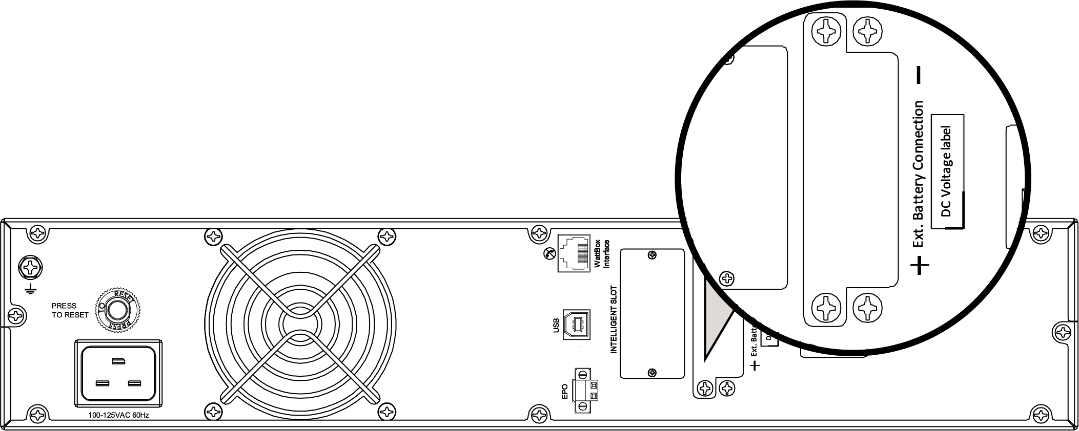
- Use a Phillips screwdriver to remove the cover of the Ext Battery Connection port on the back of the UPS.
-
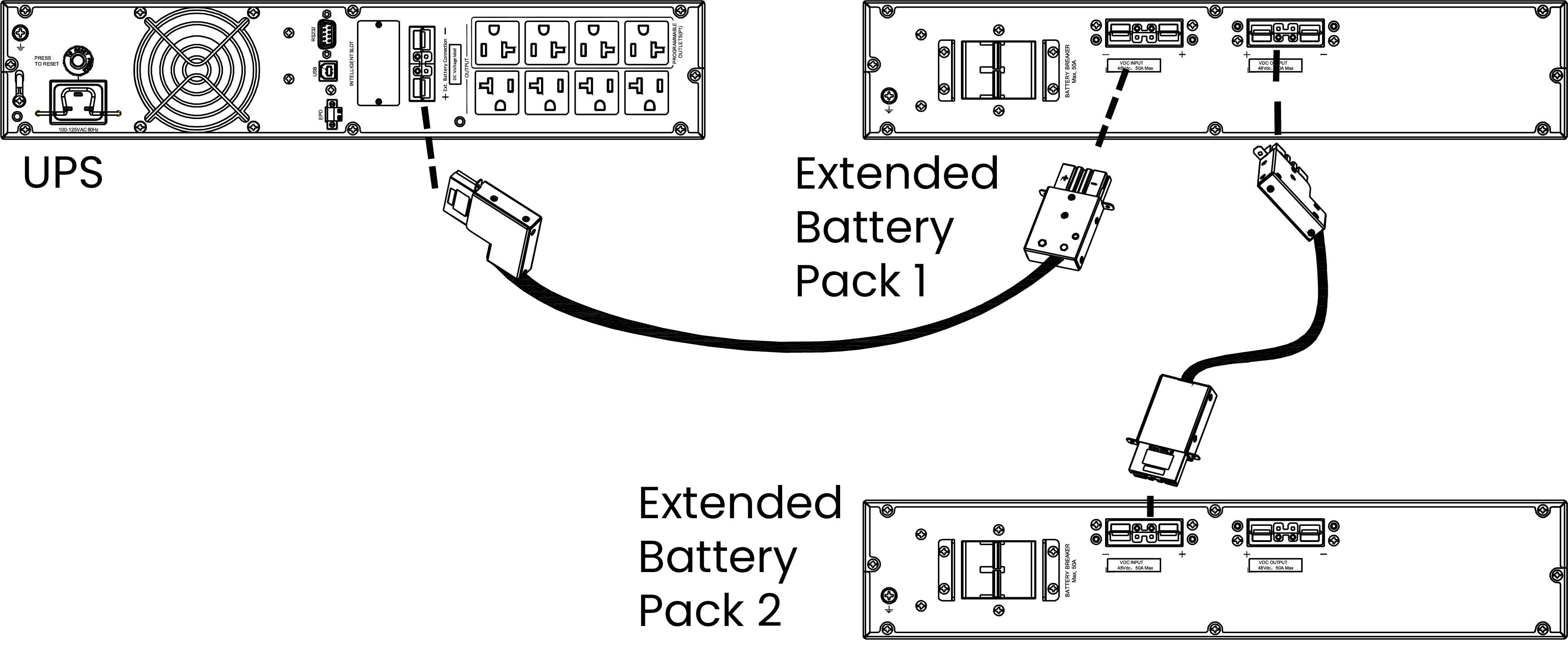
Plug the cable connector into the Ext Battery Connection port of the UPS and the battery pack(s).
Note: A maximum of five Extended Battery Packs can be daisy-chained off of one UPS. Connect multiple battery packs in series by connecting the second battery connection port of the first battery pack to the first battery connection port of the second battery pack.
-
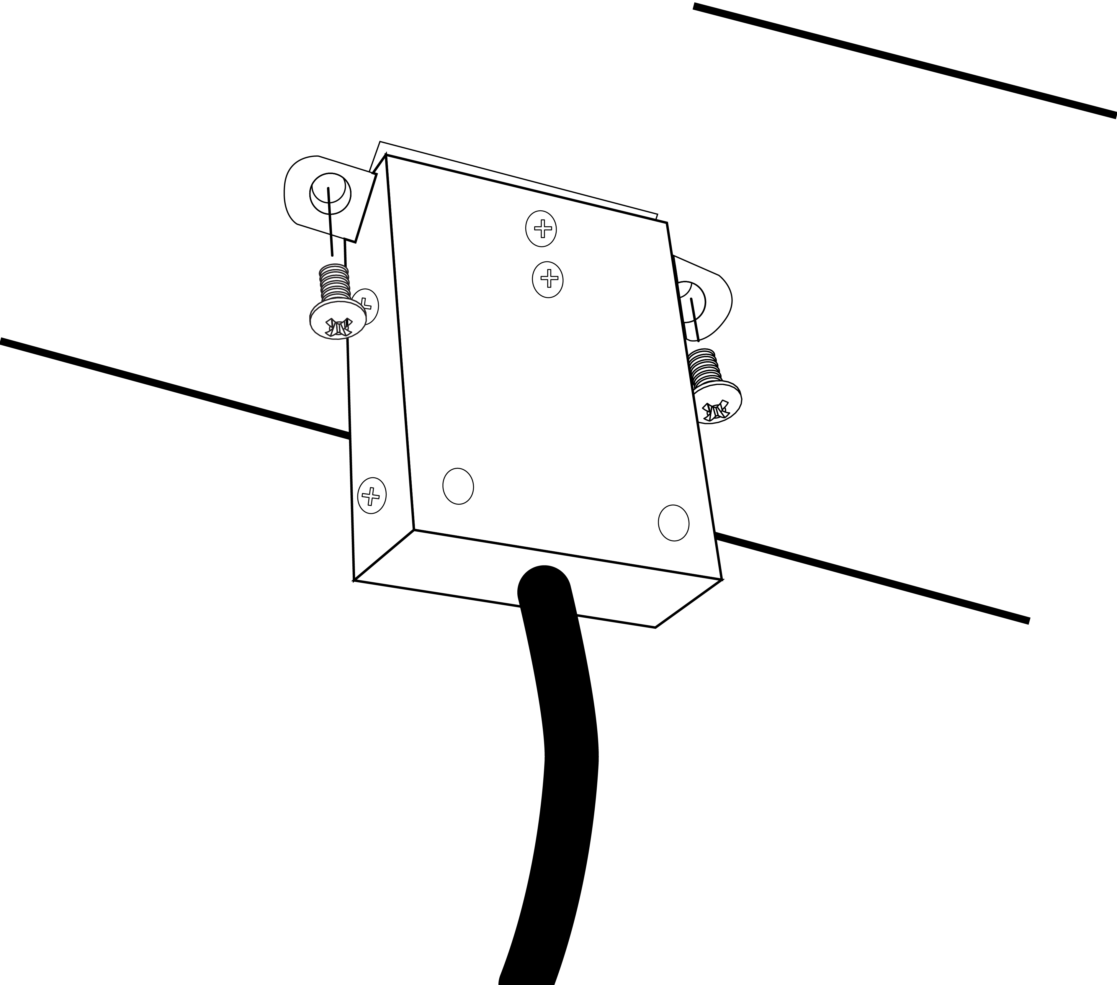
Secure the connector housings to the unit and the battery pack(s) with screws.
-
On the back of each Extended Battery Pack, set the breaker to On.
Note: The UPS auto-detects the Extended Battery Packs. The safe recharge rate is automatically configured based on the number of Extended Battery Packs detected.
Disable or enable the Emergency Power Off (EPO) function
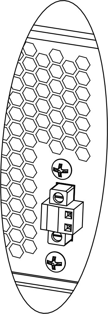
The EPO feature uses a simple open/closed circuit that, when opened, causes the UPS to immediately shut off power to all outlets.
By default, the UPS is delivered with Pin 1 and Pin 2 closed (a metal plate is connected to Pin 1 and Pin 2) for normal operation. To activate the EPO function, remove the two screws on the EPO port to remove the metal plate connecting the pins.
EPO Reset
To restore normal operation after engaging EPO, the UPS must be turned off and back on using the front panel LCD buttons.
Note: Configure the EPO function logic through the LCD. Refer to program 16 in UPS settings for details.
UPS input connection
Plug the UPS into a two-pole, three-wire, grounded receptacle only. Avoid using extension cords.
For 100/110/115/120/125/127VAC models, the power cord attaches to the UPS input plug (NEMA 5-15P for 1K and 1.5K models).
Note: If the Site Wiring Fault indicator (
 ) lights up in LCD panel, the UPS is plugged into an improperly wired power outlet. Refer to the Troubleshooting section for more information.
Turning on the UPS
Press the ON/Mute button for two seconds to power on the UPS.
Note: The battery fully charges during the first five hours of normal operation. Do not expect full battery capability during this initial charge period.