Specifications and Requirements
Specifications
|
Model Numbers |
C4-T5IW11-WH, C4-T5IW8-WH |
|---|---|
|
Screen |
Resolution: 1920 × 1200, capacitive touch |
|
Camera |
720p |
|
Network |
Ethernet or Wi-Fi • 802.11b/g/n 2.4 GHz • 802.11a/n/ac 5 GHz • Security: WEP, WPA/WPA2 PSK, 802.1x EAP, PEAP Notes: (1) While technically the touchscreen can use 802.11b, 802.11b is not supported. (2) 802.11n is recommended for best performance. Even with 802.11n, broadcasting to several devices will degrade Video Intercom response time and images. Broadcasting to additional devices will further degrade performance. See “Wireless Network Limitations.” |
|
Power supply |
PoE (IEEE 802.3af) 12 W peak |
|
Dimensions |
8" model: 211.1 × 146.5 × 14 mm (8.311 × 5.768 × 0.55 in) 8" model (mounted on wall): 211.1 × 146.5 × 14.7 mm (8.311 × 5.768 × 0.57 in) 11" model: 268.4 × 183.5 × 14.8 mm (10.567 × 7.224 × 0.583 in) 11" model (mounted on wall): 268.4 × 183.5 × 15.5 mm (10.57 × 7.22 inches × 0.61 in) |
|
Weight (with mounting bracket) |
8" model: 0.63 kg (1.4 lb) 11" model: 0.86 kg (1.9 lb) AC adapter: 0.09 kg (0.2 lb) |
|
Operating temperature |
0 to 40 ˚C (32 to 104 ˚F) |
|
Storage temperature |
-20 to 70 ˚C (-4 to 158 ˚F) |
Requirements
-
A controller fully installed and configured with Control4 OS 4.2.0 or later.
-
Control4 Touchscreen wall box (or US-style 2-gang wall box) installed. See “Accessories.”
-
If using Ethernet with PoE power:
-
Ethernet network installed and available that includes a gateway/router/switch
-
20W PoE injector or switch. PoE injector must be UL/ANSI-certified.
-
Two Ethernet Cat 5/6 cables: (1) one that runs from the Ethernet gateway/router/switch to the PoE injector/switch and (2) one that runs from the PoE injector/switch to the Ethernet connection in the touchscreen’s wall box.
-
-
If using Wi-Fi with a PoE injector:
-
Wireless network (IEEE 802.11a/b/g/n/ac) installed and available with a wireless access point (AP).Security can be WEP, WPA/WPA2 PSK, 801.1x EAP, or PEAP.
-
Front view
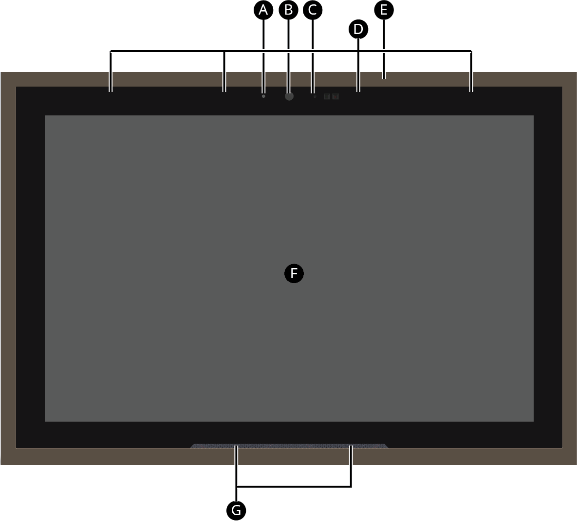
A Indicator LED (startup, camera in use)
B Camera
C Proximity and ambient light sensor
D Far-field microphones
E Swappable trim ring
F 8" or 11" diagonal, capacitive 1920 × 1200 display
G Speakers
Back view
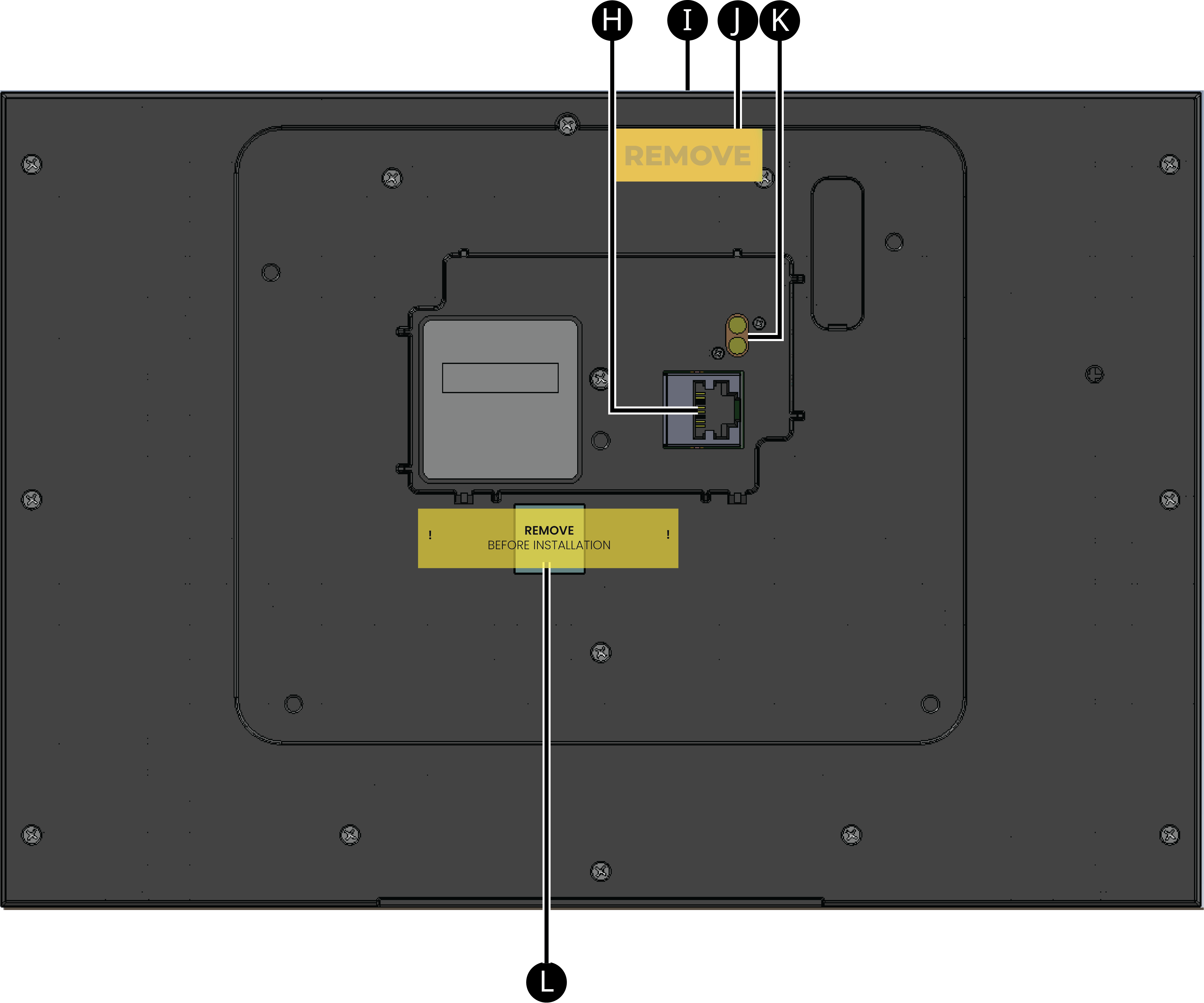
H PoE Ethernet port
I Locking screw (secures touchscreen to wall mounting bracket)
J Locking screw retention block
K AC adapter pins (only used with optional AC power supply adapter)
L Thermal pad (remove liner before finishing install)
Top view (without trim ring)

M Locking screw (secures touchscreen to wall mounting bracket)
N Reset pinhole - Press to reboot, press and hold until "Erasing" appears on screen to restore to factory defaults.
Touchscreen placement
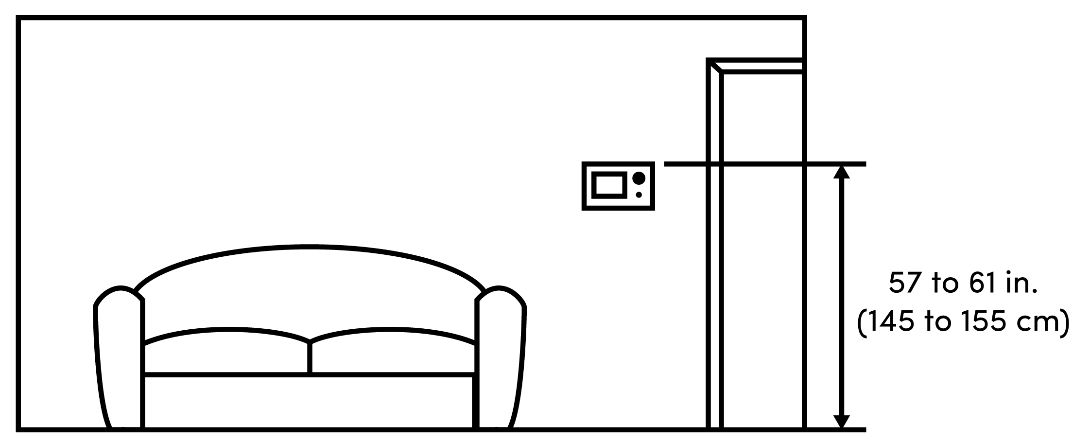
Place the touchscreen in a convenient location at eye level, typically near the entrance of the room, about 145 to 155 cm (57 to 61 inches) from the floor (Figure 3).
Note: Consider the camera on the panel and the height of the people in the home who will use the camera for Video Intercom.
Important Important: The top of the touchscreen must be mounted no higher than 2 m (6.6 ft.) above the floor.
Figure 1: Touchscreen placement
LED indicator
The LED on the touchscreen indicates the camera status of the camera and booting information as described in the next table.
| Camera/LED color state | Touchscreen status |
|---|---|
| Off | Camera is off |
| White solid | Camera is on |
| White flashing (1 Hz) | Touchscreen is booting |
| White flashing slow (0.5 Hz) | Factory reset |
| White fast blink (0.25hz, 4 per second), slow blink (0.5hz, 2 per second) | Touchscreen error |