820 hybrid turret contents
-
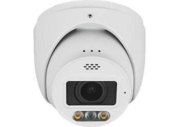
camera
-
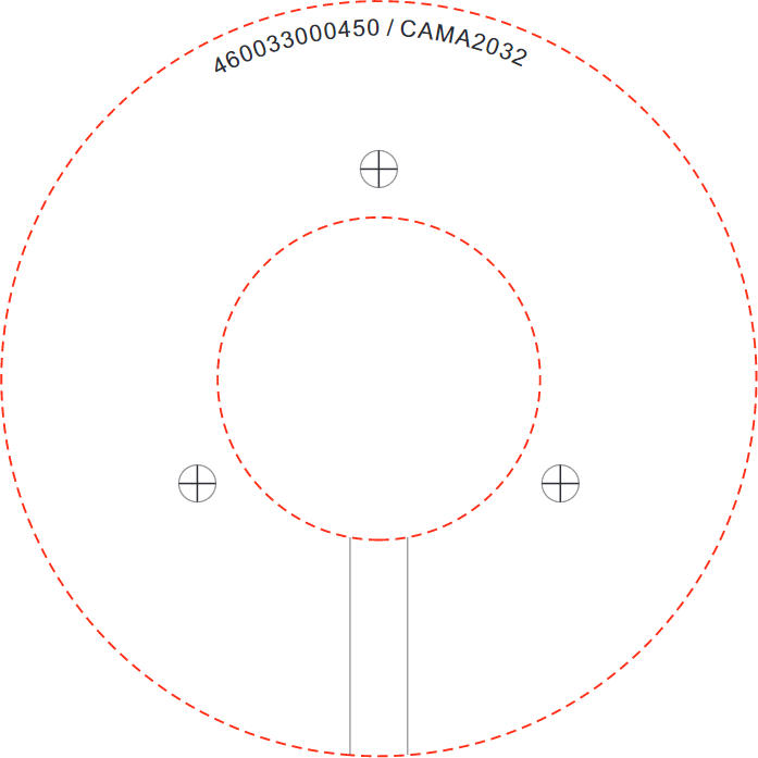
adhesive mounting template
-
3 × wall anchors with screws
-
weatherproofing kit
-
hex wrench

PoE advisory
Caution: If you are using PoE, ensure that your NVR has enough capacity, otherwise your cameras may randomly disconnect from your system.
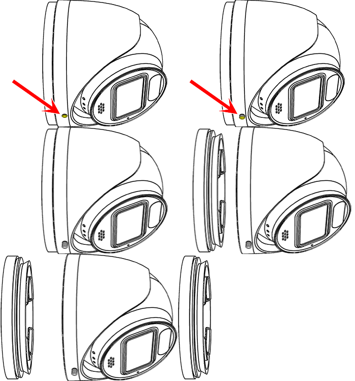
Detach the mounting base
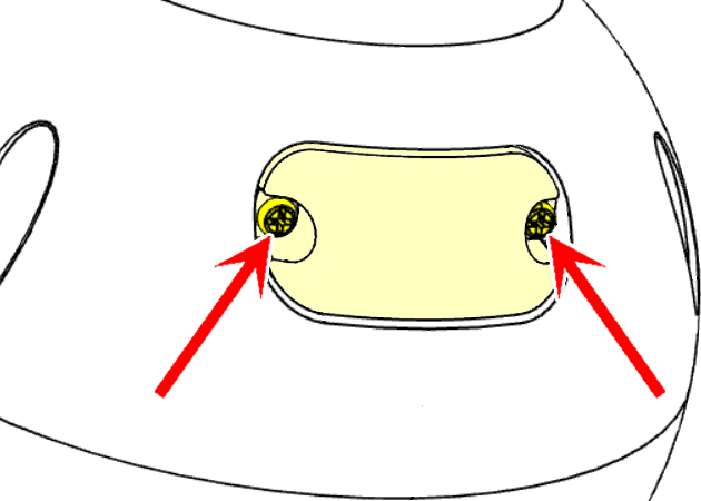
Loosen but do not remove the lock screw.
Remove the mounting base from the shell.
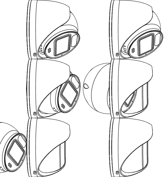
Remove the camera
Remove the camera ball through the bottom of the shell.
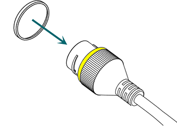
Weatherproofing: Prepare the tail
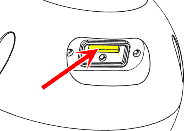
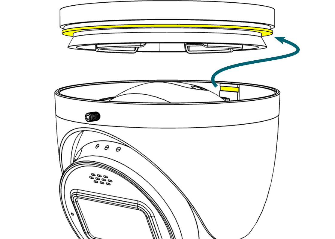
Find the white washer in the weatherproofing kit.
Place it on the network connector of the camera's tail. The proper placement is shown here in yellow.
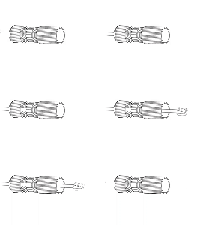
Weatherproofing: Insert the network cable
Slide a terminated category cable through the end cap and the casing.
For best results, terminate the Ethernet cable to the T568A standard.
Caution: Triple-check that your NVR has enough PoE capacity.
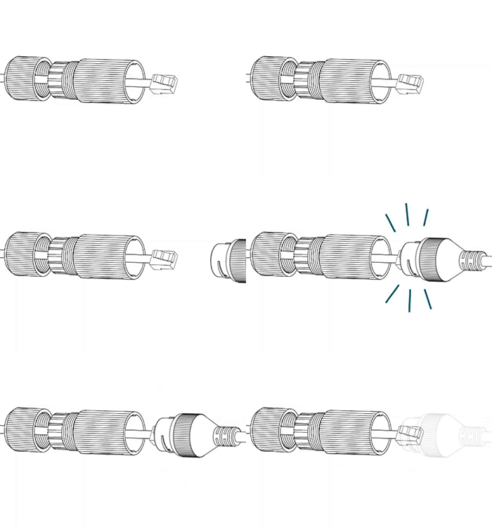
Weatherproofing: Connect the tail
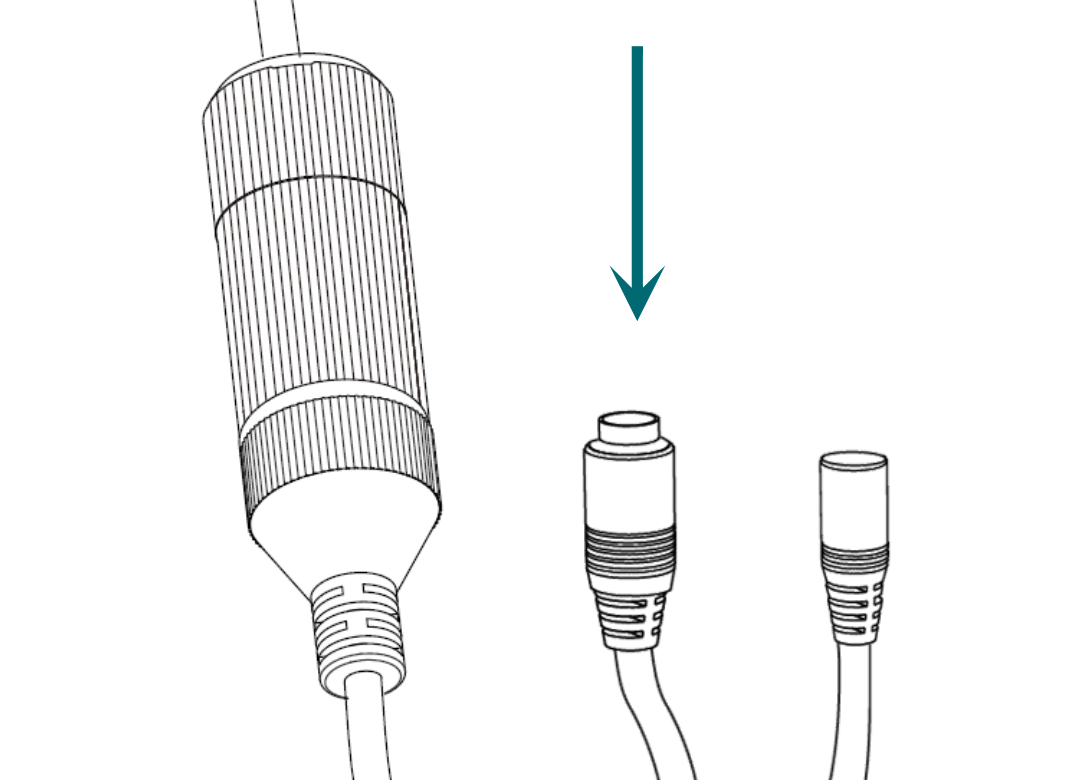
Connect the terminated cable to the network connector of your camera's tail.
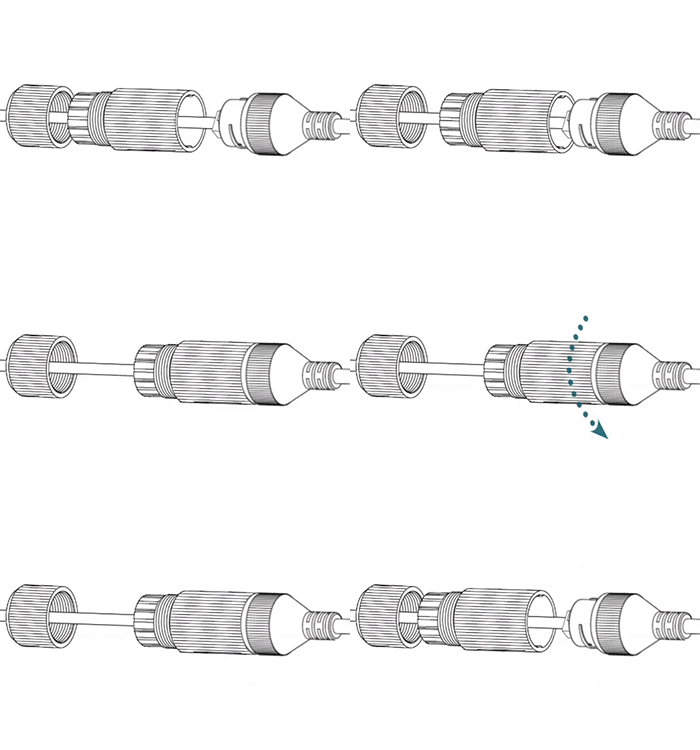
Weatherproofing: Secure the casing
Slide the weatherproof casing firmly onto the camera's network connector. Twist it to lock it in place.
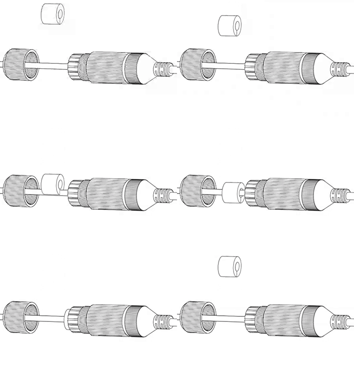
Weatherproofing: Insert the sealing gasket
The sealing gasket has a slit in the side. Use this slit to place the gasket around the cable, then slide the gasket fully into the weatherproof casing.
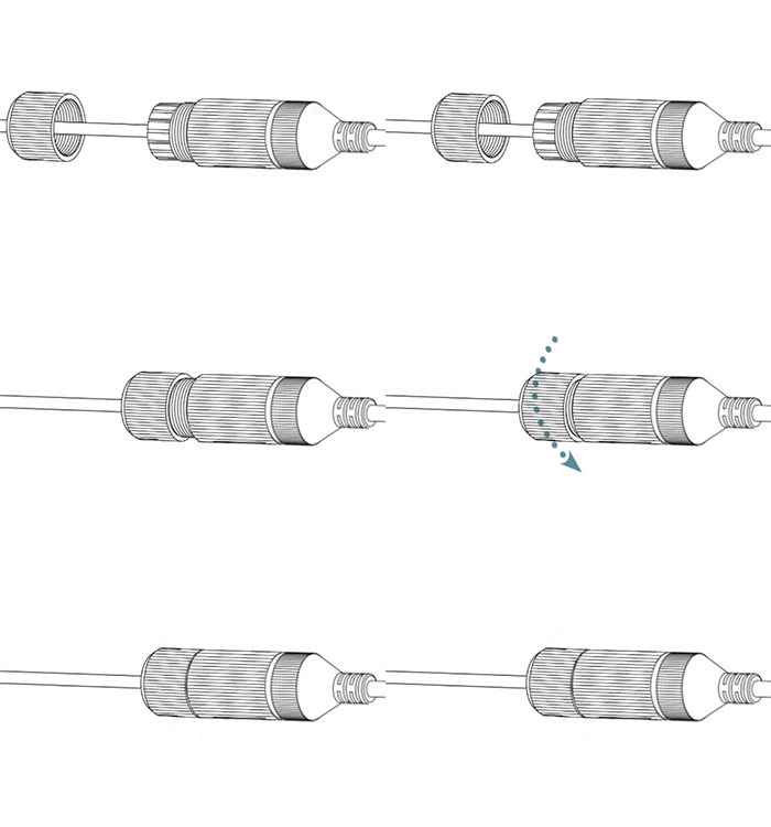
Weatherproofing: Attach the end cap
Screw the end cap onto the casing until it is snug. The compresses the gasket around the cable, providing a weatherproof seal.
Connect the power (if needed)
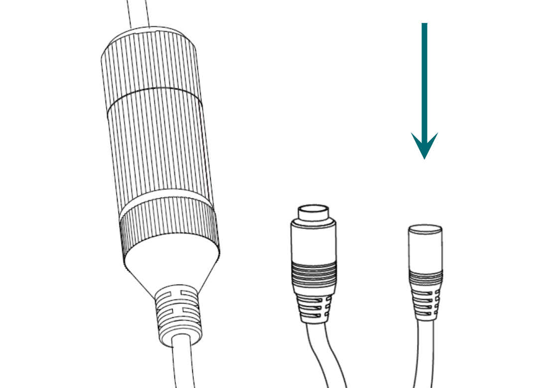
If not using PoE, attach the power connector.
Pro Tip: Wrap any unused connectors to prevent short circuits.

Claim the camera in OvrC
If you have an OvrC Pro device, it automatically claims your camera. If not, claim it by manually entering its MAC address and service tag number. Once claimed, activate the camera in OvrC to help you adjust its aim.
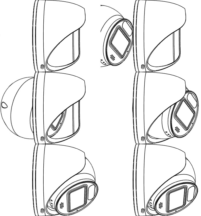
Replace the camera
Return the camera ball to its position inside the shell.
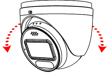
Aim the camera shell
Rotate the shell to aim the camera at the surveillance area.
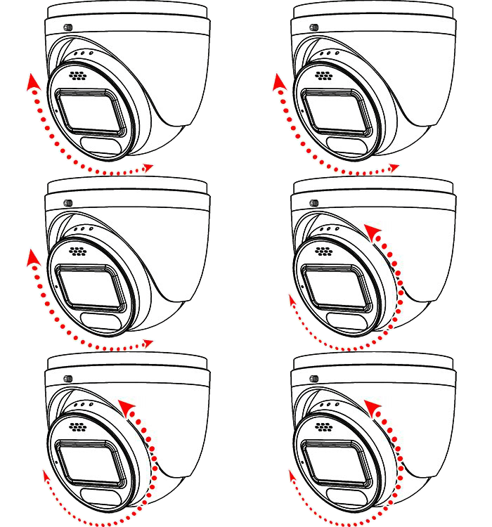
Angle and level the camera
Angle the camera ball up or down to get the exact scene needed. Spin the ball within the housing to level the image.
Pro Tip: By default, the speaker goes above the lens.
.gif)
Tighten the lock screw
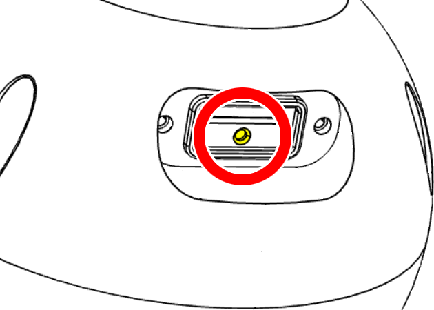
Secure the camera's position with the lock screw. Your installation is complete.
| Warranty | Support | Tech Community |
Copyright © 2025, Snap One, LLC. All rights reserved.
