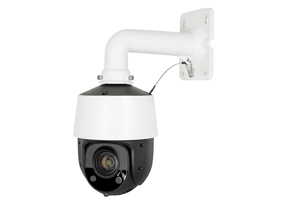
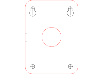
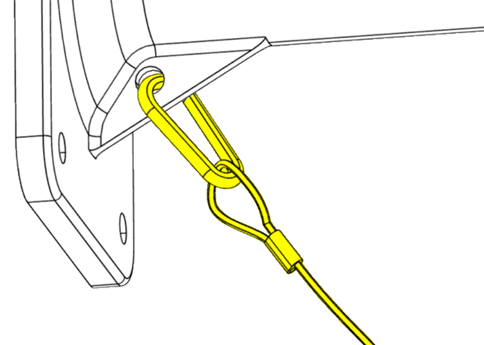
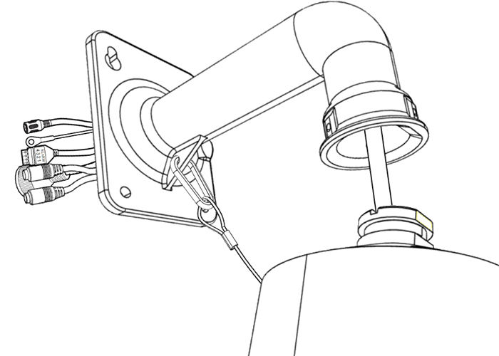
420-PTZ-25 contents
-
Camera
-
Arm mount w/ 3 × hex-cap screws
-
Mounting template
-
Weatherproofing kit
-
4 × concrete anchors with screws
-
Hex key

PoE advisory
Caution: If you are using PoE, ensure that your NVR has enough capacity, otherwise your cameras may randomly disconnect from your system.
Plan for proper placement
For the best results with your camera's auto-tracking feature, install this camera a minimum of 15' / 4.5m above ground. Higher elevations improve performance.
Prepare the surface
Use the mounting template to drill pilot holes (and a cable hole if needed).
Insert all four plastic wall anchors. Insert screws into the top two holes. Leave at least 3/4" (2 cm) of the screws exposed.
Thread the wires
Thread the tail from the camera through the wall mount.
To make this task easier, space the ends of the wires out so they're not bunched up, then wrap them in electrical tape so they slide through the mount more easily.
Attach the camera
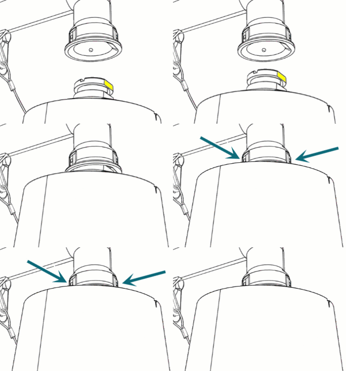
Insert the camera into the wall mount. The flat portion of the PTZ should face the end of the arm mount (this marks the "front" of the PTZ camera).
Secure the PTZ in place with the three pre-installed machine screws.
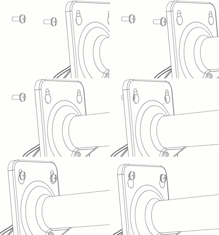
Hang the bracket
Slide the top screws through the keyholes in the wall mount.
Leave the wires from the wall and the camera tail dangling out.
Remove the tape
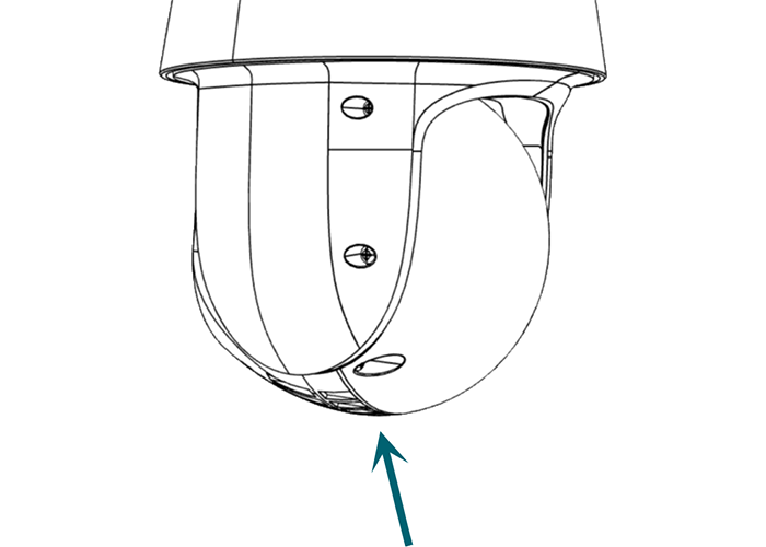
Now that the camera and mount are safely attached to the wall, remove the packing tape that prevents the camera ball from moving during shipment.
Remove the utility cover (optional)
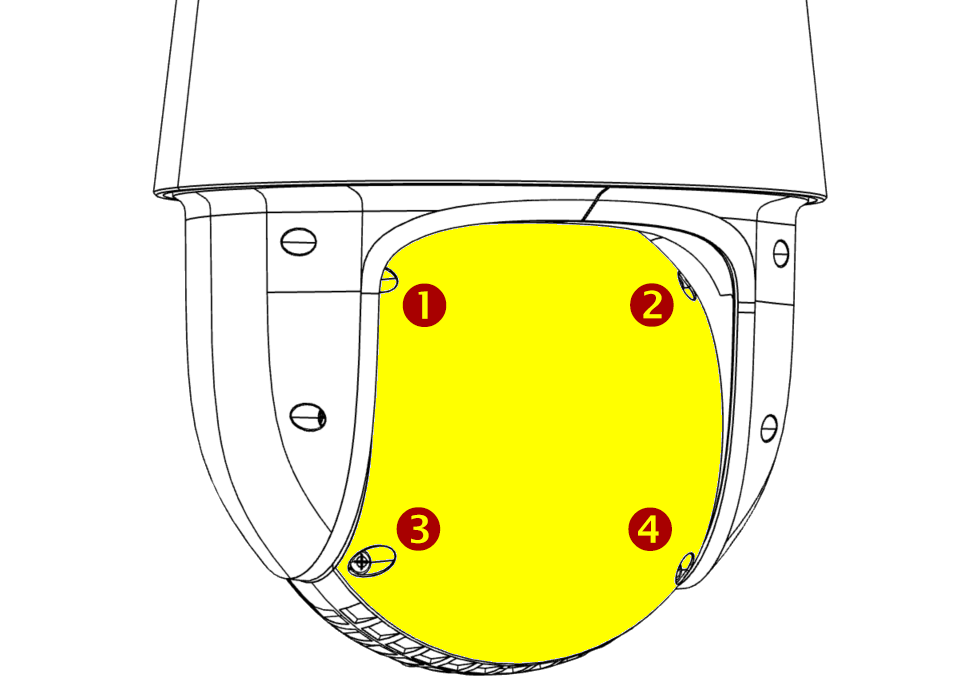
If you need to access the SD card slot or the reset button, loosen these four screws and remove the utility cover.
Install an SD card (optional)
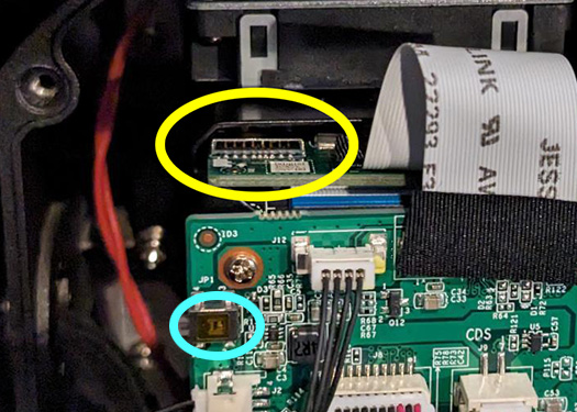
The SD card slot (circled in yellow) can take a card up to 256GB. Use only a surveillance-rated SD card.
Press the reset button (circled in cyan) and hold it for 30 seconds to reset the camera to defaults.
Replace the utility cover.
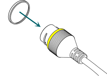
Weatherproofing: Prepare the tail
Find the white washer in the weatherproofing kit.
Place it on the network connector of the camera's tail. The proper placement is shown here in yellow.
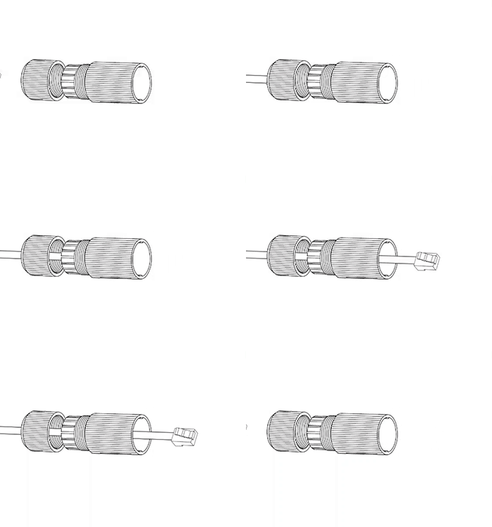
Weatherproofing: Insert the network cable
Slide a terminated category cable through the end cap and the casing.
Caution: If your system does not support PoE+, add a LUM-A20-POE60W power injector to your cable.
Caution: Triple-check that your NVR has enough PoE capacity.
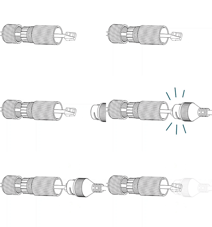
Weatherproofing: Connect the tail
Connect the terminated cable to the network connector of your camera's tail.
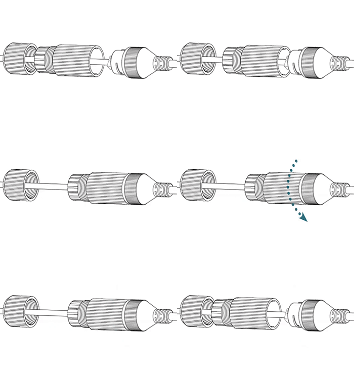
Weatherproofing: Secure the casing
Slide the weatherproof casing firmly onto the camera's network connector. Twist it to lock it in place.
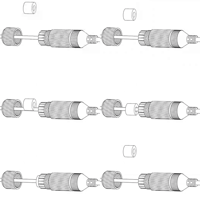
Weatherproofing: Insert the sealing gasket
The sealing gasket has a slit in the side. Use this slit to place the gasket around the cable, then slide the gasket fully into the weatherproof casing.
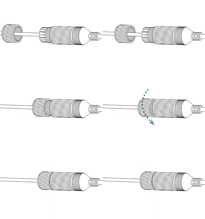
Weatherproofing: Attach the end cap
Screw the end cap onto the casing until it is snug. The compresses the gasket around the cable, providing a weatherproof seal.
Connect the audio (optional)
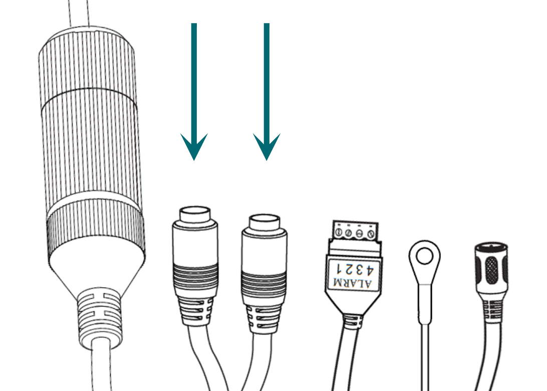
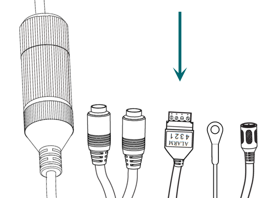
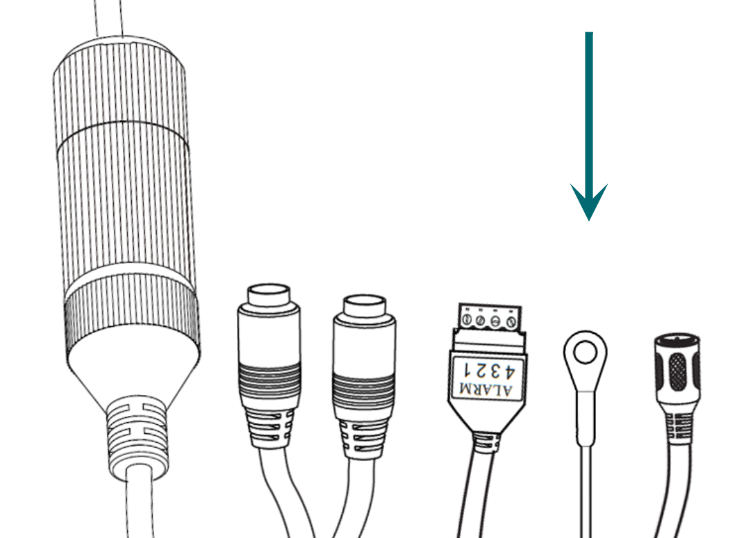
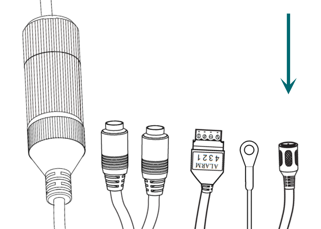
To add external audio to the feed, connect your local microphone to "IN" and your amplifier to "OUT". The wires are labeled with a small tag.
Connect the alarm (optional)
If you wish to add an alarm or other such system to the camera, attach it to the Phoenix connector.
Connect the power (if needed)
If using 12V power rather than PoE+, attach the power adapter.
Pro Tip: Wrap any unused connectors to prevent short circuits.
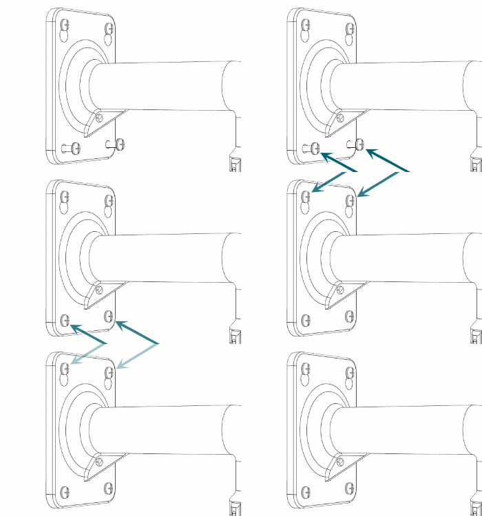
Secure the bracket
Tuck the wires and tail into the wall or bracket, as needed.
Insert and tighten the bottom screws. Tighten the top screws.

Claim the camera in OvrC
If you have an OvrC Pro device, it automatically claims your camera. If not, claim it by manually entering its MAC address and service tag number. Once claimed, activate the camera in OvrC to help you adjust its aim.
