TRIAD SUBAMP User Interface
Sub Amps
Link – (TS-SUBAMP2400 only) When enabled, the Link button applies settings to both amplifier channels. When disabled, settings can be individually set for each amplifier channel.
Note: Link must be enabled when using a dual voice coil subwoofer
Channel 1 / Channel 2 - (TS-SUBAMP2400 only) Selects the amplifier channel to configure.
OvrC icon – Shows your current OvrC status: blue - connected, red - disconnected.
User icon - Configure username and password.
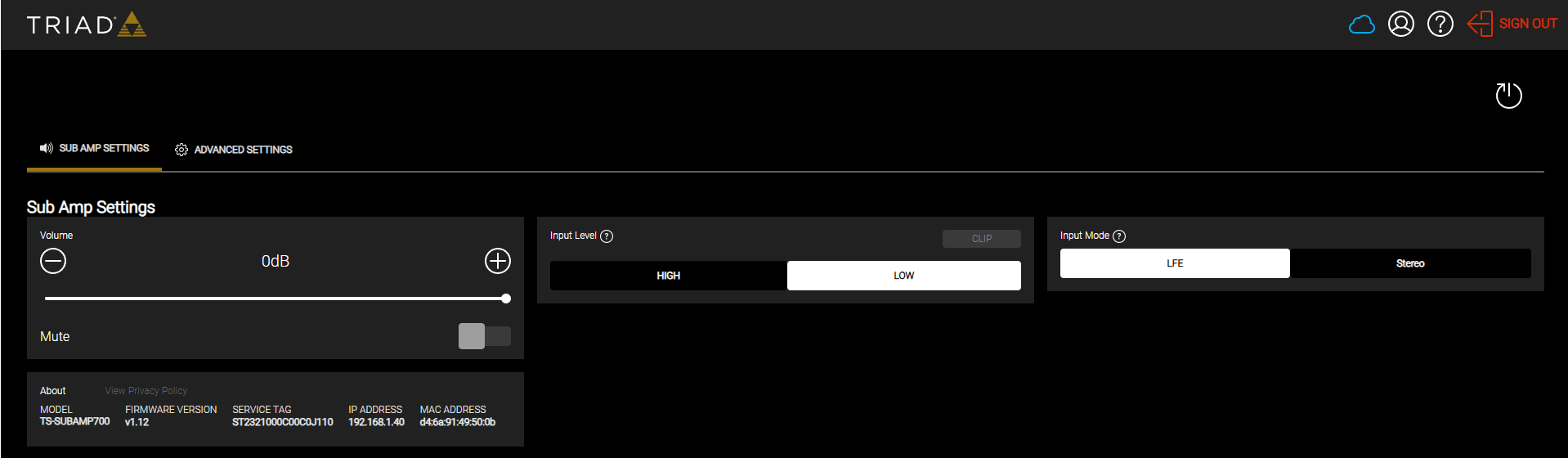
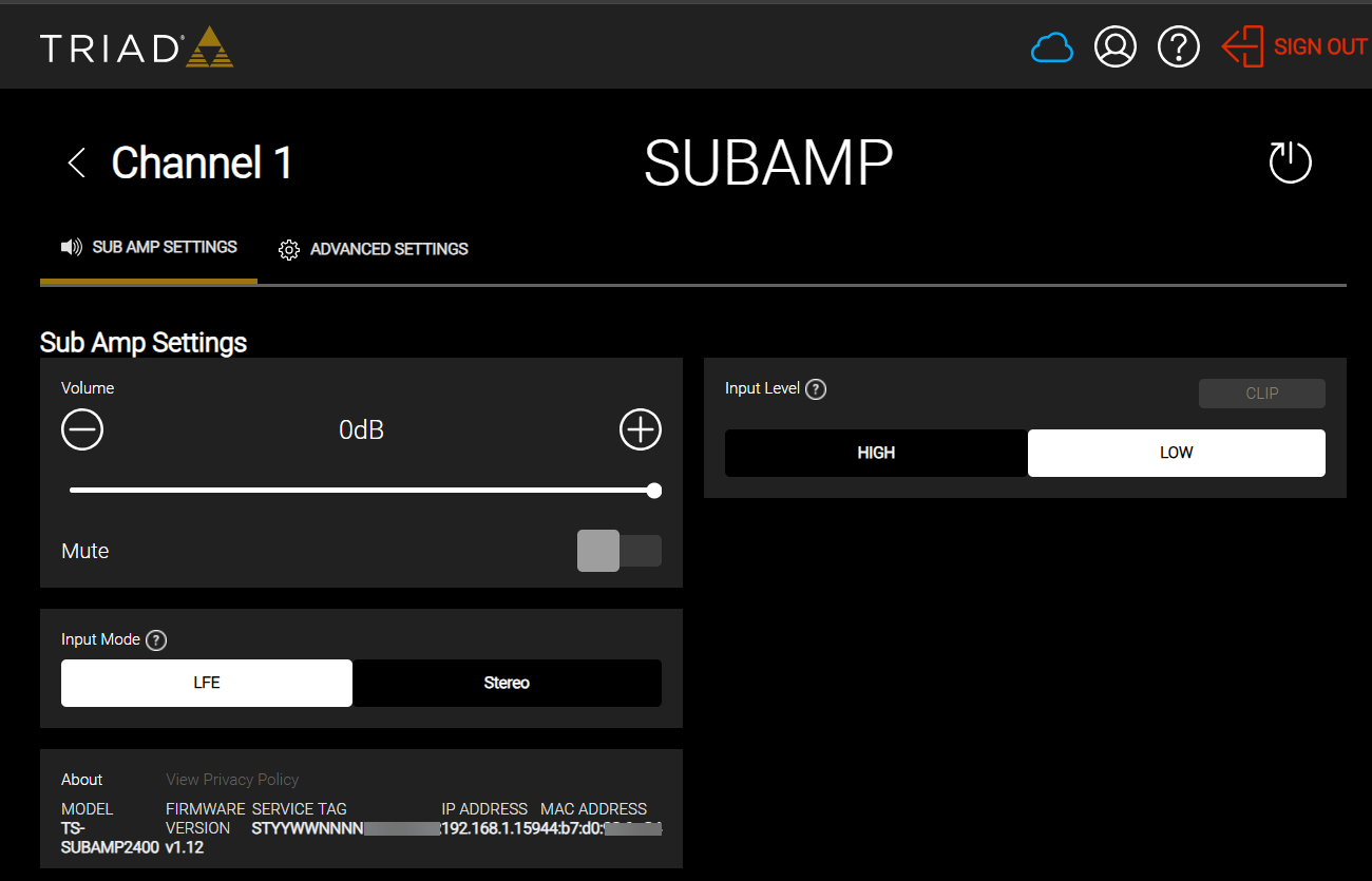
Channel 1
Sub Amp Settings
-
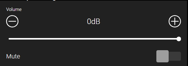
Volume – Sets subwoofer output volume
-
Mute – Mutes the audio output
-
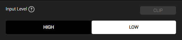
Input Level - The High / Low input level is used to maximize the amplifier power output based on your source’s output level. Please check the owner’s manual of your source device to determine its output level and select the correct setting
Input level when using balanced RCA inputs:
|
Model |
Input (Low) |
Input (High) |
Output Voltage |
Output Power @ 3Ohms |
|---|---|---|---|---|
|
TS-SUBAMP2400 |
-10 dBv (316 mVrms) |
-4 dBv (631 mVrms) |
60Vrms (per channel) |
1200W (per channel) |
|
TS-SUBAMP1200 |
-10 dBv (316 mVrms) |
-4 dBv (631 mVrms) |
60Vrms |
1200W |
|
TS-SUBAMP700 |
-10 dBv (316 mVrms) |
-4 dBv (63 1mVrms) |
45.8Vrms |
700W |
Input level when using balanced XLR inputs:
|
Model |
Input(Low) |
Input (High) |
Output Voltage |
Output Power @ 3Ohms |
|---|---|---|---|---|
|
TS-SUBAMP2400 |
0 dBv (1Vrms) |
+6 dBv (2Vrms) |
60Vrms (per channel) |
1200W (per channel) |
|
TS-SUBAMP1200 |
0 dBv (1Vrms) |
+6 dBv (2Vrms) |
60Vrms |
1200W |
|
TS-SUBAMP700 |
0 dBv (1Vrms) |
+6 dBv (2Vrms) |
45.8Vrms |
700W |
-
Clip - Indicates whether amplifier input signal is clipping or not. Reduce your sources output settings or change the input level setting from Low to High.
-
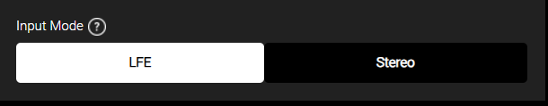
Input Mode
-
LFE – Select if connected to a single LFE output from your source device
-
Stereo - Select if connected to a Stereo output from your source device
-
Note: The input levels shown in the balanced and unbalanced tables will be met in each input mode setting, respectively. The Stereo mode will be a summation of L and R to meet the input level where the LFE mode will meet the input level with the designated single input.
Advanced Settings
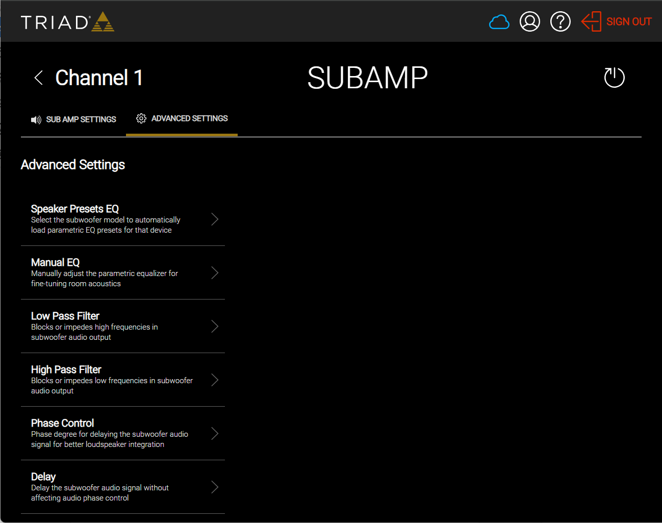
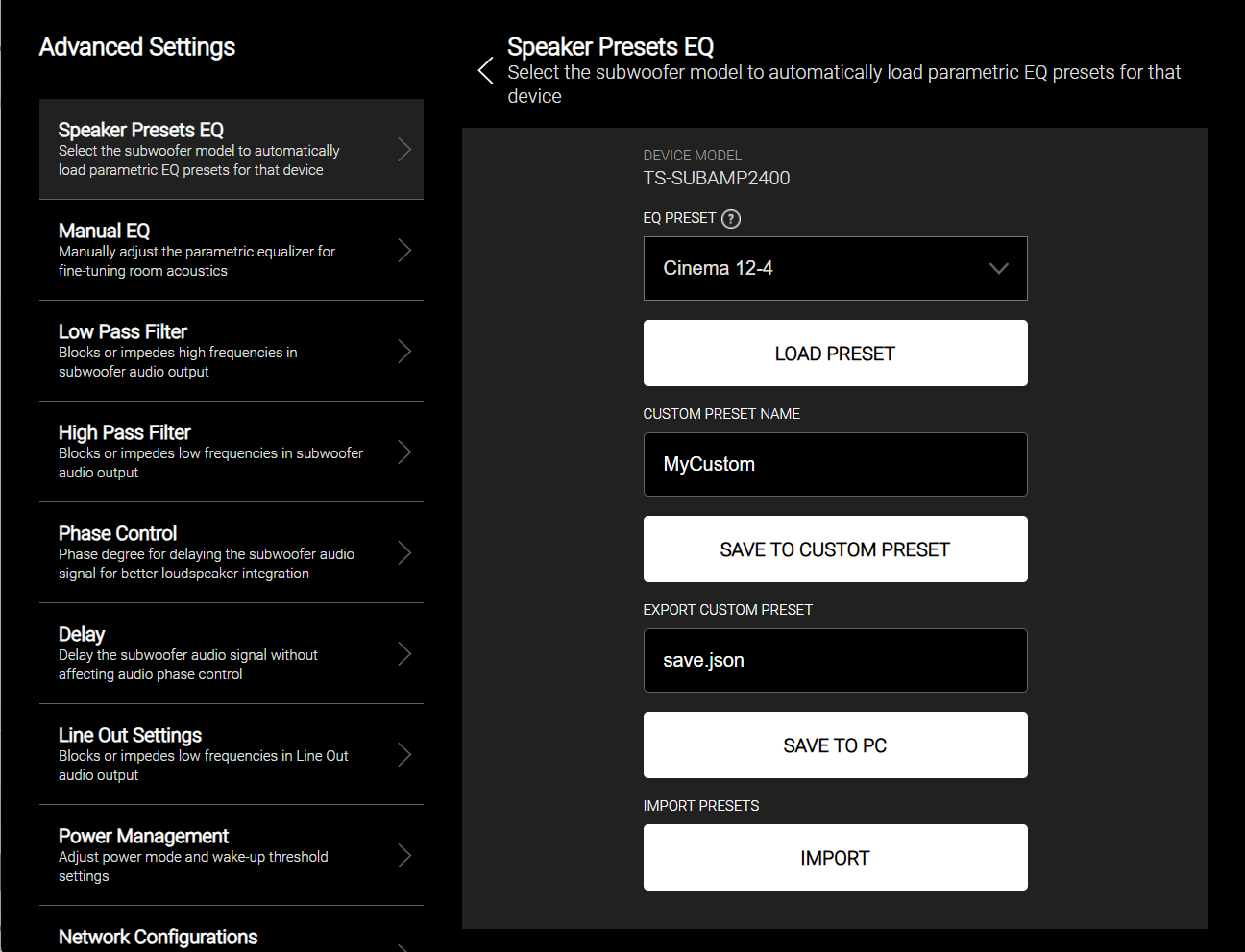
Speaker Presets EQ
Speaker preset EQs are used to optimize your subwoofer’s performance. We have carefully optimized the DSP settings and other parameters to take the work out of configuring them yourself. For Triad passive subwoofers, select the model from the drop-down list. For Triad In-room active subwoofers the preset EQ is pre-installed.
Alternatively, a set of custom presets can be saved from your settings or imported to overwrite the default presets on the amplifier.
EQ Preset - Select your subwoofer model from the drop-down list and select Load Preset to enable the settings on the amplifier.
Custom Preset Name – Save your settings as a custom preset. Enter a name for the preset and click Save to Custom Preset.
Export Custom Preset – Export the selected preset to your computer.
Import Presets – Imports a preset or group of presets from your computer.
Manual EQ
The manual EQ allows you to fine-tune the default EQ settings.
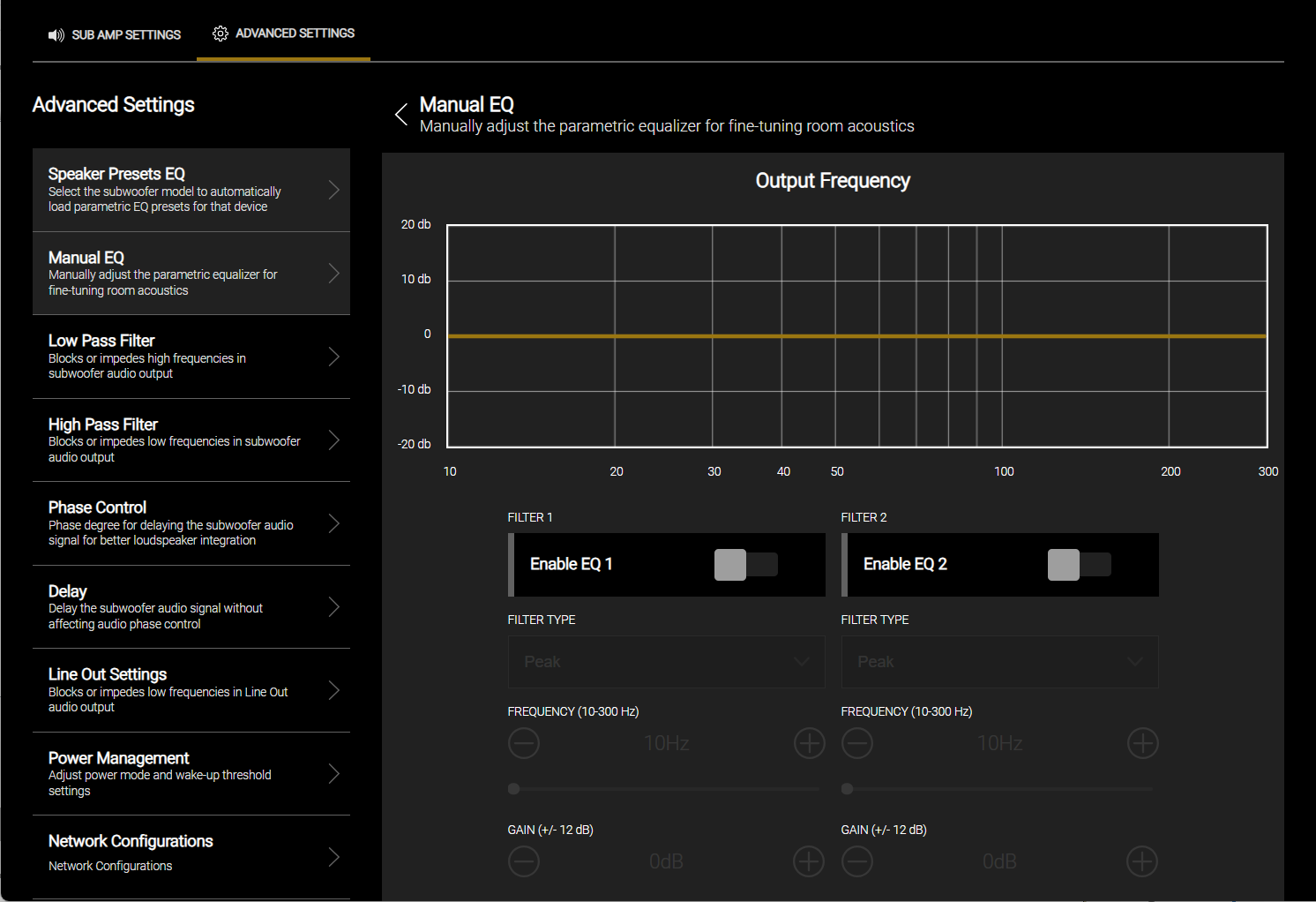
Filter Type
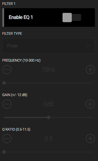
Peak - The Peak filter passes all frequencies but boost or cut at the set frequency point, depending on the gain setting. The Q setting determines the filter's shape or bandwidth, controlling how wide or narrow the filter is. Use these filters to adjust the subwoofer's in-room frequency response.
Bass - This is a low-shelf filter that boosts all the frequencies below the frequency set point. It has a fixed Q for the filter shape for the roll off. This shelving filter is used to increase bass output.
Treble - This is a high-shelf filter that boosts all the frequencies above the frequency set point. It has a fixed Q for the filter shape for the roll off. This shelving filter increases treble output.
Notch - Use this filter to focus on narrow band frequencies and remove problematic frequencies. The frequency set point is the center of the notch where the width and shape of the filter is set with the Q.
HPF - High Pass Filter. This filter type removes low frequency below the frequency set point. They are used to isolate high frequencies from the incoming audio stream.
LPF – Low pass filter. This filter type removes high frequencies above the frequency set point. They are used to isolate bass from the incoming audio stream. In the case of the subwoofer this allows you to only provide the frequencies that the subwoofer is responsible for playing.
Frequency (10-300 Hz) - Adjusts the center frequency for any given EQ Band.
Gain (+/- 12 dB) - Adjusts the gain for the EQ band.
Q Ratio (0.5-11.5) - Adjusts the width of the EQ Filter.
Low Pass Filter
The Low Pass Filter determines the low frequency crossover point for the subwoofer. For the best experience:
-
Enable the low pass filter when the amplifier is providing the crossover.
-
Disable the low pass filter if the AVR or processor is controlling the Crossover point.
-
If an AVR or processor is controlling the Crossover point, set the subwoofer's Low Pass Filter at least one octave above the AVR's crossover point.
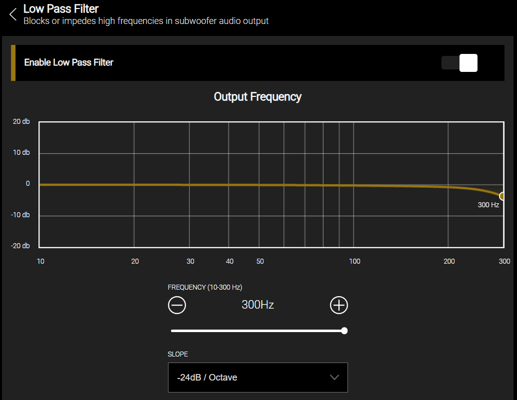
Enable Low Pass Filter - Turns the Low Pass filter On or Off.
Frequency (10-300 Hz) - Selects the Crossover Frequency.
Slope (12dB / 24dB / 36 dB) - Selects the slope of the Crossover Frequency.
High Pass Filter
The High Pass filter, sometimes referred to as a “SubSonic” filter, is a high-pass filter that prevents extremely low frequencies from being reproduced by the subwoofer. This prevents extremely low frequencies that cannot be heard but consume tremendous amounts of power. Enabling the High Pass Filter transfers power to the frequencies you can hear and feel.
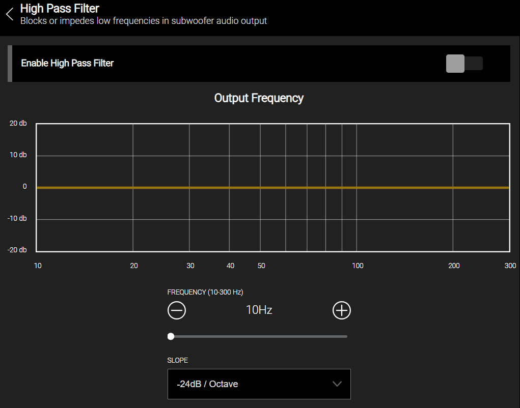
Enable High Pass Filter - Turns the High Pass Filter On or OFF.
Frequency (10-300 Hz) - Selects the Crossover Frequency.
Slope (12dB / 24dB / 36 dB) - Selects the slope of the Crossover Frequency.
Phase Control
Use phase control to adjust the phase of the subwoofer's output at the crossover point, so it is in sync with the other speakers in your system. This helps reduce phase cancellation and improve the overall sound quality.
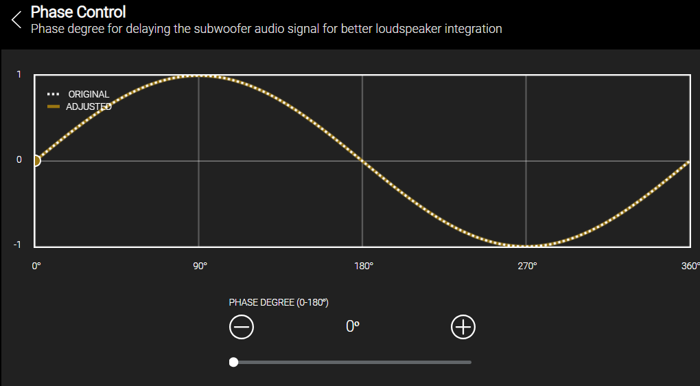
Phase Degree (0-180°) - To set the phase control on your subwoofer, listen to music, or other content. If you hear a cancellation effect, adjust the phase control frequency until the effect is minimized.
Delay
Use the delay setting to compensate for the time difference between the sound from the subwoofer and the other speakers. This eliminates a possible echo or phasing effect.
Note: This setting operates independently from the phase control setting.
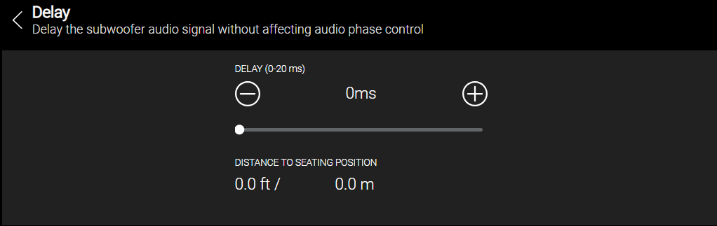
To adjust for delay, measure the distance between the subwoofer and your listening position, then use the slider to match that distance.
Pro Tip: Try adjusting the Distance to Seating Position by +/- 2 ms for the best sound.
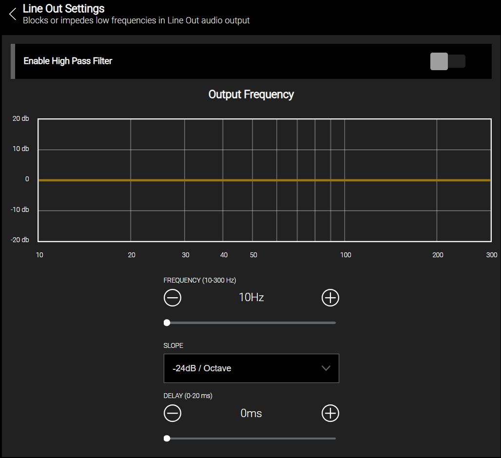
Line Out Settings
The line out settings are used to enable a high pass filter on the amplifier’s audio output RCAs or Balanced outputs. These are typically used when another amplifier without a high pass filter is installed downstream from the subwoofer or subwoofer amplifier.
-
Enable High Pass Filter - Turns the High Pass Filter on or off.
-
Frequency (10-300 Hz) - Selects the Crossover Frequency.
-
Slope (12dB / 24dB / 36 dB) - Selects the slope of the Crossover Frequency.
-
Delay -
Power Management
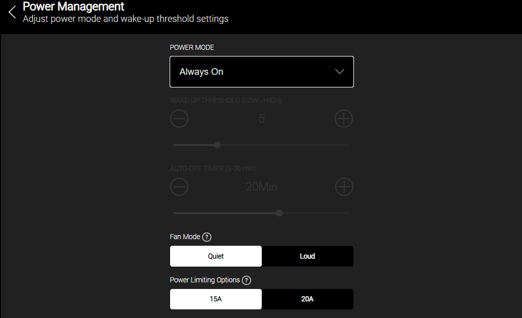
Power Mode - Sets the On/Off behavior of the
-
Always On - The
-
Auto Signal Sense - The
-
12V Trigger - The
Note: If you're using a wireless transmitter, Auto Signal Sense is disabled. Use Always On or 12V Trigger.
Additional Auto Signal Sense settings
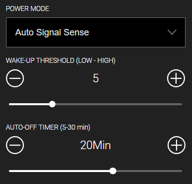
Wake-Up Threshold (Low-High) - Determines how much signal is required to change the
-
Reducing the wake-up threshold makes the
-
Increasing the wake-up threshold makes the
Auto-Off Timer (5-30 min) - The amount of time it takes for the
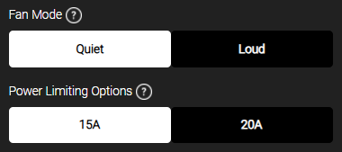
Fan Mode (TS-SUBAMP2400 Only) - The protection mode setting determines the maximum fan speed used to cool the amplifier.
-
Quiet - When set to quiet, the fan speed won't exceed 45dBA, but the
-
Loud - When set to loud, the fan speed spins faster to provide maximum cooling to the
Power Limiting Options (TS-SUBAMP2400 Only) - The amplifier is compatible with a typical 110V 15A electrical circuit, or more powerful 20A electrical circuit. To achieve fully specified amplifier power a 20A electrical circuit is required.
-
15A - For compatibility with most electrical circuits, the amplifier ships in 15A mode. Be sure to use the provided 15A power cord and connect it to a 15A electrical circuit. Amplifier power will be reduced slightly to not trip an electrical breaker at full power.
-
20A - When set in 20A mode the amplifier will produce the fully specified power. Be sure to use the provided 20A power cord and connect it to a 20A electrical circuit
Network Settings
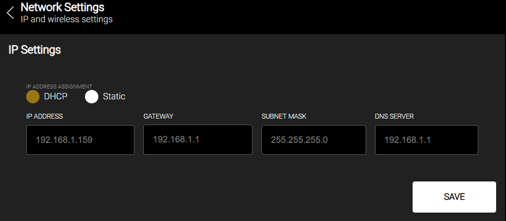
IP Address Assignment
DHCP - Select this option to let a DHCP server on the local network automatically assign a network address to the amplifier.
Static - Select this option to manually configure an IP address, gateway, subnet mask, and DNS server for the amplifier.
-
IP Address - Enter the IP address for the SUBAMP.
-
Gateway - Enter the local gateway address.
-
Subnet Mask - Enter the subnet mask for the local network.
-
DNS Server - Enter the DNS server address.
Custom Name
You can set a custom name for your amplifier. This can help identify the amplifier if you have more than one amplifier installed.
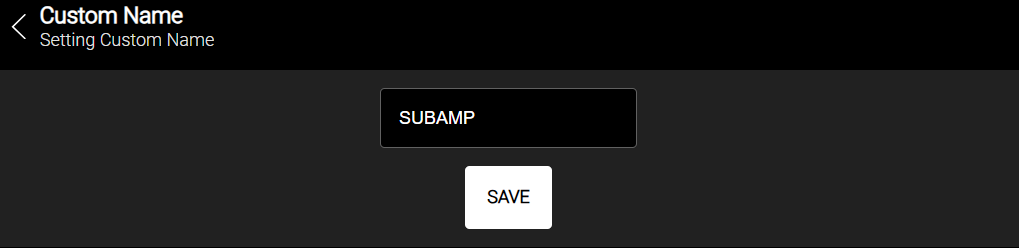
Note: Do not use special characters in the Custom Name.
Firmware Update
Firmware updates can be found on the Snap One website under Support > Product Files & Video. You can also update the
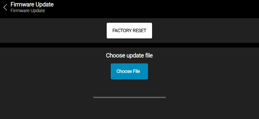
Factory Reset - Click to reset all settings including audio and network settings.
Choose update file - To manually update a firmware image, click on Choose File, browse to and select the firmware update file, and click Update Image.