Installing the Luma Bridge
Front view of the Luma Bridge
A Activity LED—The Activity LED shows when the controller is processing.
B Caution LED—This LED shows solid red, then blinks blue during the boot process. The Caution LED blinks orange during the factory restore process.
C Link LED—The LED indicates that the controller has been identified in a Control4 project and is communicating with Director.
D Power LED—The blue LED indicates that power is present (AC or PoE). The controller turns on immediately after power is applied to it.
Back view of the Luma Bridge
APower port—AC power connector for an IEC 60320-C5 power cord.
B USB port
C ID button and RESET—ID button is pressed to identify the device in Composer Pro. The ID button on the Bridge is also an LED that displays feedback useful during a factory restore. The RESET pinhole is used to reset or factory restore the Bridge.
D ENET/POE+ IN—RJ-45 jack for a 10/100/1000BaseT Ethernet connection. Also can power the controller with PoE+.
Installing the Luma Bridge
-
Ensure that the home network is in place before starting system setup. An Ethernet connection to the local network is required.
-
The bridge can be installed in a rack or set on a shelf. The CORE 1 Rack Mount Kit is sold separately and is designed for easy installation of up to two CORE controllers or Luma Bridges side by side in a rack.
-
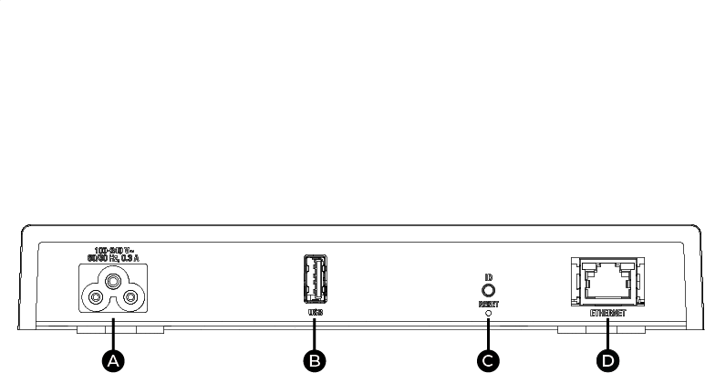
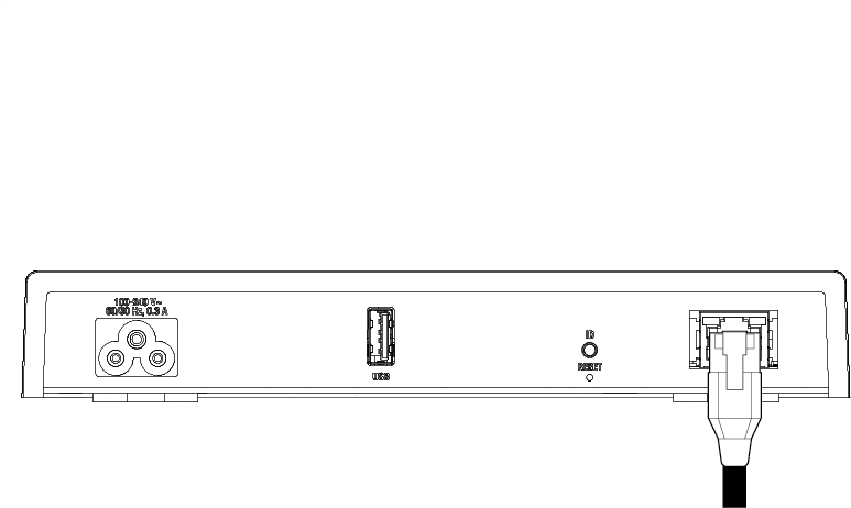
Connect the bridge to the network, connecting an Ethernet network cable into the bridge’s RJ-45 port (labeled ENET/POE+ IN) and into the network port on the wall or at the network switch.
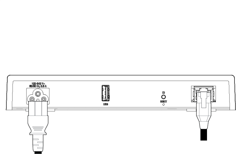
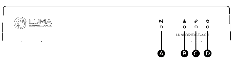
Power on the Luma Bridge
After finishing the installation, power on the Luma Bridge by either (a) connecting the power cord or (2) turning on the PoE power source.