Understanding Spanning Tree Protocol (STP) & Best Practices
Spanning Tree Protocol (STP) is a Layer 2 protocol that decides the best path for LAN traffic when multiple options exist, preventing network loops while guaranteeing redundancy in case of link failure.
How does it do this?
STP communicates using Bridge Protocol Data Units (BPDU). STP-enabled switches send BPDUs to elect a root bridge for the network, using BPDUs. All STP decisions made for the network are from the viewpoint of the root bridge, including which ports to block and which ports to forward information to.
There are multiple versions of STP. Be sure to use the same version across all switches to avoid timing issues.
STP versions:
-
Spanning Tree Protocol (STP) — IEEE 802.1d.
-
Rapid Spanning Tree Protocol (RSTP) — IEEE 802.1w. Enhances the original protocol with faster convergence and network recovery.
-
Multiple Spanning Tree Protocol (MSTP) — IEEE 802.1s. Improves upon RTSP by allowing the creation of multiple “instances” of RTSP across multiple VLANs.
How the root bridge is elected
By default, STP-enabled switches use the Bridge ID and MAC address of a switch to automatically elect a root bridge, using BPDUs. This isn’t the best practice, as you want the root bridge to be near the center of your network topology to optimize the flow of traffic across the network. Instead, use the Bridge Priority to manually elect the core switch as the root bridge.
Bridge Priority
The default Bridge Priority for Araknis and Pakedge switches is 32768. This can be adjusted in increments of 4096. To ensure your core switch is selected as the root bridge, set its Bridge Priority to 4096.
Caution: Do not set the Bridge Priority to 0. This value is typically reserved for the router for some flexibility in the STP topology, should you need to make temporary changes. Like needing to replace the core switch.
STP topology best practices
-
Use Router-On-A-Stick Topology. Place the most powerful managed switch between the router and the rest of the LAN to serve as the core switch. Connect additional equipment to the managed switch.
-
Set the core switch’s Bridge Priority to 4096.
-
Do not put an unmanaged switch between managed switches.
-
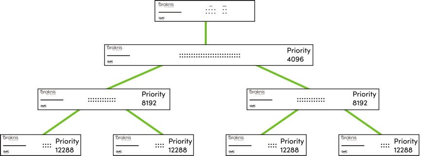
Increment the Bridge Priority by 4096 at every switch tier. (i.e. 4096 for the core switch, 8192 for the second tier of switches, 12288 for the third tier of switches, etc.)
-
Disable Edge Port and Auto Edge on each port.
Note: STP traffic can flow through an unmanaged switch and the devices connected to it, but a device can only benefit from STP by being connected to an STP-enabled port on managed switch.
What happens if the core switch fails?
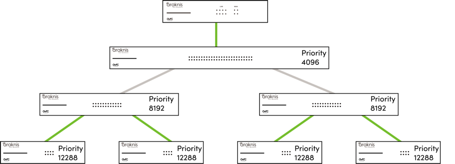
To make a loop-free environment, the edge switches elect the switch with the lowest priority as the new root bridge. The topology above would break into two separate instances of STP because they have no link between them.
If all the switches in these topologies have the default Bridge Priority, the new topology could create two sub-optimal instances of STP.
Redundant links
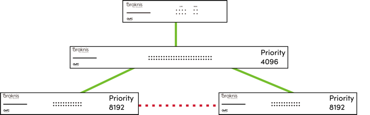
STP allows you to create a physical backup link (redundant link) between switches without causing a network loop. It does so by putting the looped port into an err-disabled state.
Err-Disabled state
STP can detect physical backup links (redundant links) between switches. STP automatically puts these redundant links into an err-disabled state, which blocks the flow of traffic to the port with the highest path cost. If the path cost of the link changes or one of the switches falls offline, STP forwards the traffic to the redundant link with the lowest bridge priority.
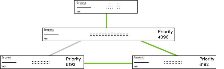
In the same scenario described above, if a link between the core switch and an edge switch fails, STP detects the link failure and re-calculates all its paths using the information provided by BPDUs. STP now sees that the redundant link (dotted line) is a viable path between the two edge switches, so it changes the port state from err-disabled to forwarding to automatically resolve an uplink failure, illustrated by the gray line in the below image.
Port settings
Most switches globally enable STP on all ports, but some can configure STP settings on individual ports and even exclude a port from STP communication. Below are descriptions of some individual port settings.
Edge port
Sometimes called PortFast, This setting forces the port’s state to forwarding, preventing the connected device(s) from communicating properly with STP. Do not enable this setting without a specific use case.
The most common use case is Troubleshooting Spanning Tree (STP) connection issues.
Pro Tip: Always disable Edge Port on switch uplinks to make sure STP can detect network loops.
Auto Edge
Auto edge attempts to automatically determine if the Edge Port setting needs to be applied. The best practice is to disable this setting to avoid unexpected network interruptions.