Advanced
Static Route
Static routes are used to create routes to other subnets using a fixed routing table.
Static routes are commonly used to pass traffic between subnets on different routers. For example, in a large office network, there is a subnet configured for the first floor inside of Router 1 using an IP address of 192.168.1.0.
Computers on the third floor are connected to Router 2 using subnet 192.168.30.0, and they need to communicate with the 192.168.1.0 subnet. A static route is configured in each router to the port connecting them.
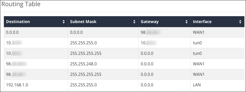
Routing Table
The routing table displays the default routing information for the router. Use this information to view and troubleshoot static routes.
Static Routing Table
This table displays configured Static Routes.
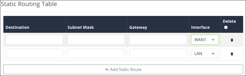
Click Add Static Route and enter the following information to create a static route:
-
Destination — The subnet you’re configuring a static route for.
-
Subnet Mask — The subnet mask of the Destination.
-
Gateway — The IP address of the subnet’s gateway. An asterisk (*) can be used as a wildcard.
-
Interface — Select the WAN or LAN port for the static route to exist on.
Click the trashcan icon to delete a static route.
NAT
Net Address Translation (NAT) allows you to map local IP addresses to a specific public IP address.
1:1 NAT
Use this table to view and configure NAT. Enable 1:1 NAT to allow the LAN IP entries to appear under the WAN IP entries.
Click Add 1:1 NAT Rule to map a LAN IP address to a WAN IP address.
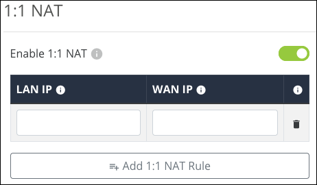
Click the trashcan icon to delete an entry.
Route Binding (520 routers only)
Use Route Binding to force a subnet route through a specific WAN interface.
Click Enable Route Binding to Add a new entry or make the previously configured entries active.
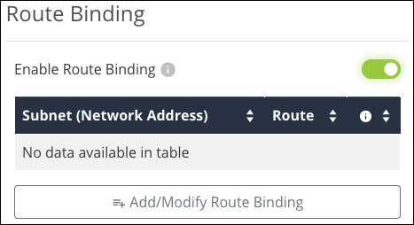
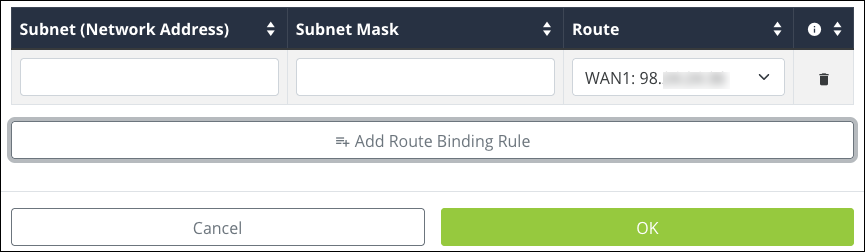
Click Add/Modify Route Binding to add or modify a Route Binding rule and modify the below information.
-
Subnet (Network Address) — The starting IP address of the subnet.
-
Subnet Mask — The subnet mask of the Subnet (Network Address).
-
Route — Select the WAN port for the traffic to pass through.
Click the trashcan icon to delete a static route.
VLANs
Virtual Local Area Networks (VLANs) are used to segment traffic on the LAN to increase the reliability and security of the network.
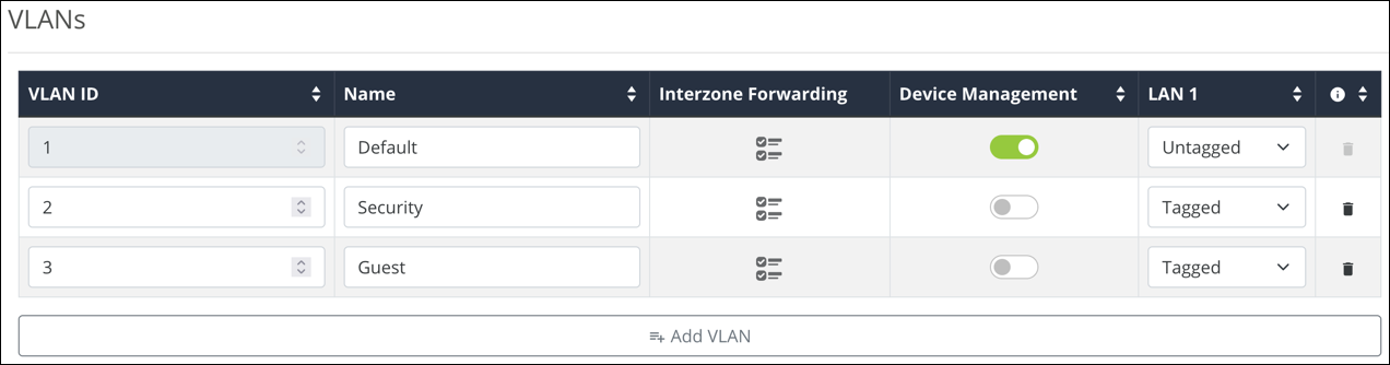
To create a new VLAN, click the + Add VLAN button, and configure the below settings:
-
VLAN ID — A unique numerical identifier for the VLAN between 1 and 4095. The default VLAN is always set to 1. The maximum number of VLANs is listed below:
-
For AN-220 routers, 32 total VLANs.
-
For AN-520 routers, 48 total VLANs.
-
-
Name — Enter a name that describes what the VLAN is being configured for. Like a Guest network or Surveillance devices. This field accepts alphanumeric (a - z and A - Z) characters, hyphens ( - ), underscores ( _ ), !, @, #, $, %, ^, &, *, (,), ?, +, and periods.
-
InterZone Forwarding (Previously InterVLAN Routing) — Click the
 icon to configure communication between client devices connected to the VLANs. Do not use this feature if security between VLANs is a concern.
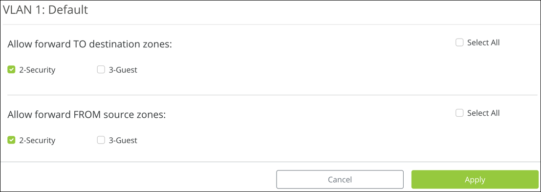
Select which VLANs to forward data TO, and the VLANs to receive data FROM. Then click Apply.
Note: You must enable this feature on each VLAN that you want to communicate with each other.
-
Device Management — Allows devices connected to this VLAN to access the router.
-
LAN 1 and 2 — Each LAN port may be configured as one of one following options:
-
Untagged — VLAN frames handled through this port are not tagged with a VLAN ID.
-
Tagged —VLAN frames handled through the port are tagged with a VLAN ID.
-
Excluded — The port is not a member of the specified VLAN. This is the default setting.
-
Note: LAN ports can only allow Untagged traffic from one VLAN.
Click the trashcan to delete an existing VLAN. The default VLAN cannot be deleted.
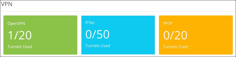
VPN
A Virtual Private Network (VPN) connects different networks through a secure tunnel over the Internet. Data sent through the VPN tunnel is encrypted for privacy even when connected to a public or shared network that isn’t secure. VPNs are commonly used to send data between networks in different geographical locations without requiring a dedicated physical connection between networks. VPNs may be configured using OpenVPN, PPTP, or IPSec standards.
Total number of supported VPNs per router:
|
Router Series |
OpenVPN |
PPTP |
IPSec |
|
220 |
20 |
5 |
x |
|
520 |
20 |
50 |
50 |
Note: The 220 series router does not support IPSec.
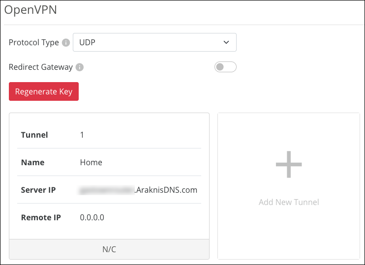
Open VPN
The Araknis router has a built-in OpenVPN server for secure, easily configured access to the network from the internet using devices with an OpenVPN client application. Use OpenVPN to access local network devices like shared drives and home network servers as if you were on the local network.
OpenVPN communicates using encrypted SSL/TLS channels between networks that hide traffic from other devices on the internet. The OpenVPN server runs on the router to control access to the tunnels, and users connect using a client application installed on their computer.
To create an OpenVPN tunnel:
-
Select a Protocol Type.
-
UDP offers faster speeds, lower latency, and is the preferred OpenVPN connection method. In rare occasions, UDP can be less reliable because the protocol does not guarantee delivery of the packets.
-
TCP offers a more stable connection, as the protocol guarantees the delivery of the packets and is less likely to be blocked by firewalls. This method tends to slow transfer rates down.
-
-
Enable Redirect Gateway, if desired. This feature ensures all internet traffic is routed through the VPN tunnel, but it also reduces VPN connection speed.
Note: If this feature is enabled after you configured the VPN you must re-export the configuration.
-
Click Add New Tunnel.
-
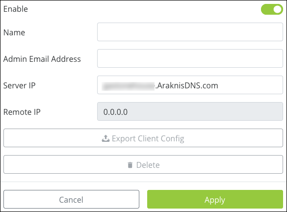
Enter a Name for the tunnel. This field accepts alphanumeric (a - z and A - Z) characters, spaces, hyphens ( - ), and underscores ( _ ).
-
The Server IP automatically populates with a public IP or a DDNS (if there is a DDNS configured in the router). The Remote IP field cannot be edited. This field accepts alphanumeric characters (a - z and A - Z), spaces, hyphens ( - ), and underscores ( _ ).
-
Click Apply.
-
Click Export Client Config and save the file in an easy-to-remember location.
The OpenVPN config file can be imported to the OpenVPN app available in the App Store, Google Play Store, or from OpenVPN when using Windows. MacOS has multiple third-party options for OpenVPN clients. Follow the instructions provided by the OpenVPN client on the machine.
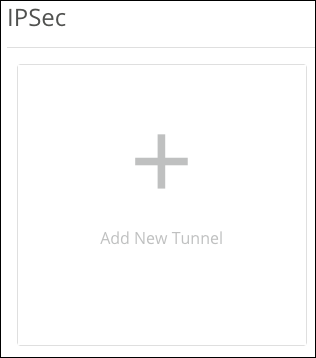
IPSec
IPSec, sometimes known as Gateway-to-Gateway, allows you to configure a VPN tunnel between two routers so that devices on each network can communicate with each other.
Note: Because IPSec VPNs connect two sites, you must configure the VPN on both routers.
Note: SHA-512 in Phase 1 does not work between Araknis x10 and x20 routers. A lower authentication should be used to ensure compatibility with x10 or 3rd party routers.
Note: Compress cannot be used when IKEv1 with Phase 2 Authentication SHA-256/SHA-512 is selected.
To create an IPSec VPN:
-
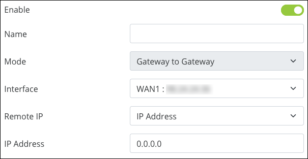
Click Add a New Tunnel and Enable it.
-
Give your tunnel a Name. This field accepts alphanumeric (a - z and A - Z) characters, hyphens ( - ), underscores ( _ ), !, @, #, $, %, ^, &, *, (,), ?, +, and periods.
Note: The Mode cannot be modified.
-
Use the Interface dropdown to select a WAN port for the tunnel to use.
-
Remote IP is the site you’re connecting to. Use the dropdown menu to select IP Address or URL (DDNS). Enter the WAN IP, or DDNS, in the IP Address field below.
-
The Local Group Setup fields auto-populate but can be modified. Selections differ based on the Local Security Gateway Type and Local Security Group Type selected.
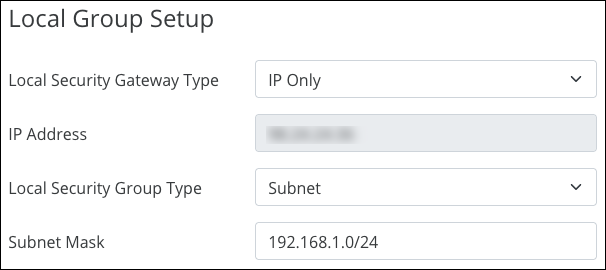
Note: Each router must use a different IP scheme to connect to the tunnel.
-
The Remote Group Setup auto-fills with the information you entered in Step 4.
The Subnet Mask field shows the CIDR notation of the Remote Group.
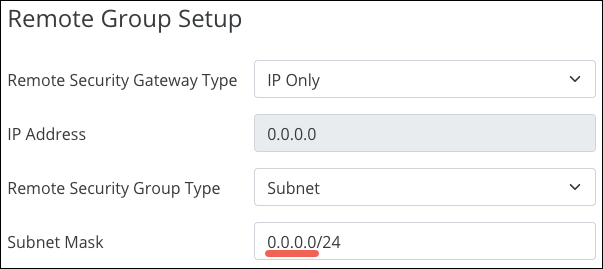
Pro Tip: Verify the last digit is zero, to include the entire IP range.
-
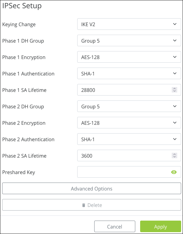
The IPSec Setup fields are customizable but can be left at their defaults. Click Apply.
Note: The Preshared Key must match on both routers. The password must be between 6 –64 characters and accepts alphanumeric (a - z and A - Z) characters, hyphens ( - ), underscores ( _ ), !, @, #, $, %, ^, &, *, (,), ?, +, and periods.
The second router’s setup should be the same. Keep in mind your Local and Remote Groups are switched and each router must use a different IP scheme to connect.
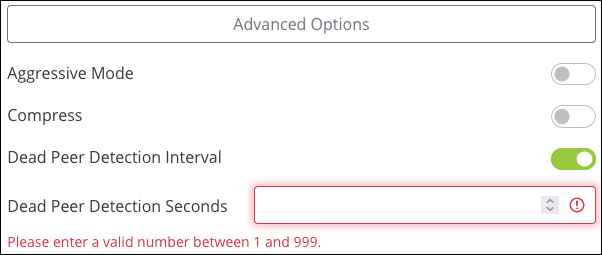
Advanced Options
-
Aggressive Mode — Enable for a less secure, but faster VPN authentication.
-
Compress — Enable to compress the traffic sent over the VPN, before it’s encrypted.
Note: Compress cannot be used when IKEv1 with Phase 2 Authentication SHA-256/SHA-512 is selected.
-
Dead Peer Detection Interval — Enable for the router to send a Dead Peer Detection Packet (DPD) to verify if the router on the other side of the tunnel is still active, then the number of seconds between DPD transmissions. If the router doesn’t get a response, it terminates the IPSec tunnel connection. The router will attempt to re-establish the connection, so the user does not have to manually connect the VPN again.
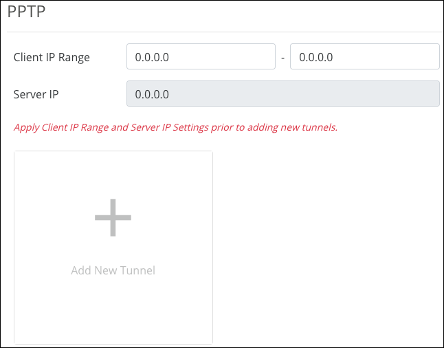
PPTP
Point-to-Point Tunneling Protocol (PPTP) is an older VPN type that does not require encryption or authentication.
Caution: PPTP tunnels are not secure. If possible, use OpenVPN or IPsec tunnels.
If using a PPTP tunnel, set the IP range for the tunnel to use, click Apply, then click the Add New Tunnel button to create a new PPTP tunnel.
To configure a PPTP tunnel, you must create the following:
-
Name — Accepts alphanumeric characters (a - z and A - Z), spaces, hyphens ( - ), underscores ( _ ), !, @, #, $, %, ^, &, *, (,), ?, +, and periods.
-
Username — alphanumeric characters (a - z and A - Z), spaces, hyphens ( - ), underscores ( _ ), !, @, #, $, %, ^, &, *, (,), ?, +, and periods.
-
Password — Must be between 8-63 characters and accepts alphanumeric (a - z and A - Z) characters, hyphens ( - ), underscores ( _ ), !, @, #, $, %, ^, &, *, (,), ?, +, and periods.
For more information on configuring PPTP tunnels on your computer, read our Tech Community article.
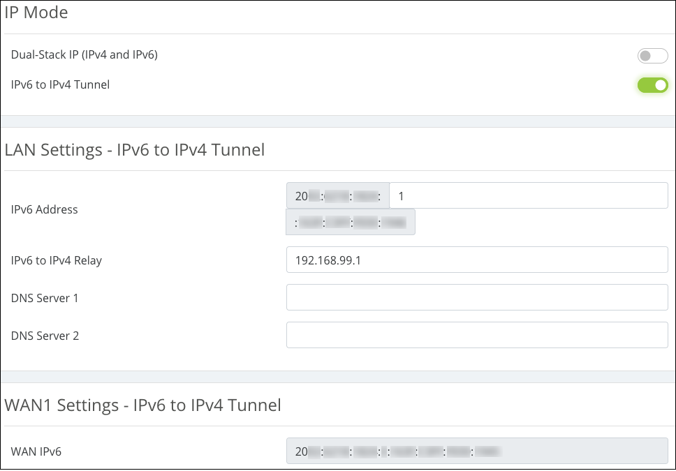
IPv6
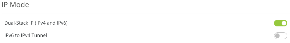
The Araknis router can handle IPv6 in one of two ways:
-
Dual-Stack IP (IPv4 and IPv6) is recommended for most applications. The router recognizes both address styles and parses out whichever address is
unnecessary. -
IPv6 to IPv4 Tunnel creates a tunnel for transferring IPv6 addresses across
an IPv4 by encapsulating the IPv6 packets into IPv4 packets, and the opposite way (IPv4 packets encapsulated in IPv6 packets).
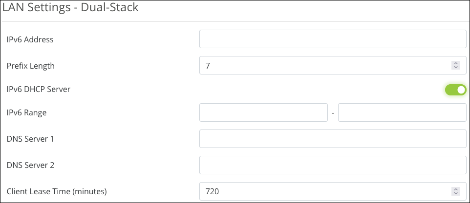
Dual-Stack IP (IPv4 and IPv6) Settings
LAN Settings
-
IPv6 Address — Enter the LAN IPv6 Address.
-
Prefix Length — Set the IPv6 equivalent to the IPv4 subnet mask. This is done by specifying the number of bits rather than using IP notation.
-
IPv6 DHCP Server — Enable or disable the IPv6 DHCP Server.
-
IPv6 Range — Enter a starting and ending IPv6 address for the DHCP server address range.
-
DNS 1 and DNS 2 — Enter the primary and secondary IPv6 DNS addresses.
-
Client Lease Time — Enter the number of minutes that a DHCP lease lasts.
WAN Settings
The options change based on the selected WAN IP Mode.
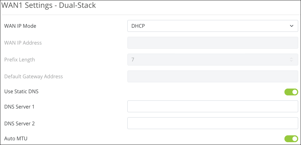
DHCP WAN IP Mode
-
Static DNS — Enable to enter specific DNS servers. You must enter the IPv6 addresses for the DNS servers.
-
Auto MTU — Leave this enabled for optimal performance. The MTU (Maximum Transmission Unit) specifies the largest packet or frame allowed to be transmitted across the WAN interface.
Static IP WAN IP Mode
-
WAN IP Address — Enter the IPv6 address to act as the root of the IPv6 WAN.
-
Prefix Length — Acts as the IPv6 subnet mask for the LAN. This IPv6 setting is executed by specifying the number of bits used for the mask (rather than using IP notation as in IPv4).
-
Default Gateway Address — Enter the IPv6 address for the router to use.
-
DNS Servers 1 and 2 — Enable to enter specific DNS servers. You must enter the IPv6 addresses for the DNS servers.
-
Auto MTU — Leave this enabled for optimal performance. The MTU (Maximum Transmission Unit) specifies the largest packet or frame allowed to be transmitted across the WAN interface.
PPoE WAN IP Mode
Using IPv6 for PPPoE is like IPv4 in that the WAN connection is authenticated using encapsulated Point-to-Point Protocol (PPP) frames.
The password has a maximum character limit of 63 and accepts alphanumeric (a - z and A - Z) characters, hyphens ( - ), underscores ( _ ), !, @, #, $, %, ^, &, *, (,), ?, +, and periods.
Consult your ISP for specific settings for configuring your WAN IPv6 service using PPPoE.
IPv6 to IPv4 Tunnel Settings
-
IPv6 Address — An IPv6 address for the tunnel. This field is automatically generated but can be edited.
-
IPv6 to IPv4 Relay — An IPv4 address for the relay server running on the router.
-
DNS Servers 1 and 2 — Enter DNS server addresses for the IPv6 requests to resolve to.
-
WAN IPv6 Address — The WAN port’s IPv6 address. This field cannot be edited.
Local DNS
Local DNS creates a server on the router for speedier results and forwarding. Use this expressly for devices in the local network (for example, to create a URL like backporchcamera.myhome.com).
In the Domain Name text box at the top, enter the URL for the device to serve as the local DNS for your network. This field accepts up to 63 characters, including alphanumeric (a - z and A - Z) characters, hyphens ( - ), and underscores ( _ ).
Click the Add Local DNS button to add an entry. Enter the host device’s name—the text you want to appear before your URL—its IP address, then select its IP mode. This field accepts up to 63 characters, including alphanumeric (a - z and A - Z) characters, hyphens ( - ), and underscores ( _ ).
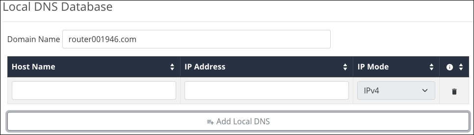
For example, if your domain is myhome.com, enter backporchcamera in the device name text box. The router auto-fills the rest of the URL.
Complete these steps for each device with a local DNS entry:
-
Reserve an IP address for each device being configured or set each device to have a static IP address. (Using a DHCP address can cause the domain name to point to a different device if the address is reissued after setup.)
-
Set the DNS server setting in each device to the same IP address as the router (default: 192.168.1.1)
SNMP
Network administrators use Simple Network Management Protocol (SNMP) to monitor the performance and settings of network devices. Configure SNMP to communicate with management on the network.
Note: SNMP communities should be managed on a network-wide basis and require coordinated settings for managers and agents on the network.
Pro Tip: Do not enable both SNMP v1/2 and SNMPv3 because SNMP3 is not backward compatible with v1 and 2. Consult the client device recommendations when choosing which SNMP version to use.
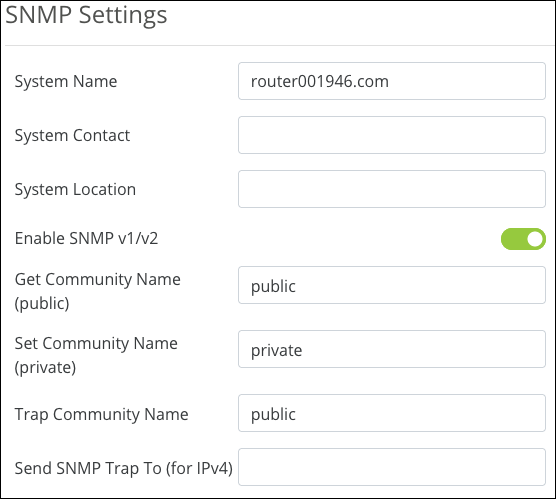
SNMP Settings
-
System Name — This field is auto-generated but can be edited. This field accepts alphanumeric characters (a - z and A - Z), spaces, hyphens ( - ), underscores ( _ ), !, @, #, $, %, ^, &, *, (,), ?, +, and periods.
-
System Contact — Enter a contact name, email address, or phone number for who should be contacted for more information about the SNMP server. This field can be left blank. This field accepts alphanumeric characters (a - z and A - Z), spaces, hyphens ( - ), underscores ( _ ), !, @, #, $, %, ^, &, *, (,), ?, +, and periods.
-
System Location — Enter the location of the server, if desired. This field can be left blank. This field accepts alphanumeric (a - z and A - Z) characters, hyphens ( - ), underscores ( _ ), !, @, #, $, %, ^, &, *, (,), ?, +, and periods.
-
Enable SNMP v1/v2 — Enable to edit the following entries.
-
Get Community Name (public) — Enter a name for the read-only community on the network.
-
Set Community Name (private) — Enter a name for the read-write community on the network.
-
Trap Community Name — Enter a name for the notifications generated by the community.
-
Send SNMP Trap to (for IPv4) — Enter an IPv4 address to send all the Trap Community messages from the SNMP-capable devices on the network.
SNMPv3 Settings
Enable to configure an SNMPv3 server.
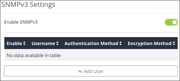
Click Add User to determine who has access and privileges to the SNMP traffic.
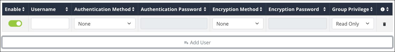
Click Add User once more, and enter a Username, Authentication Method, Encryption Method, and the Privileges they should have (Read Only or Read/Write). Then click Apply.
These fields have the following character limitations:
-
SNMPv3 Username — Alphanumeric (a - z and A - Z) characters
-
SNMPv3 Auth Password — Between 8-32 characters. Accepts alphanumeric (a - z and A - Z) characters, hyphens ( - ), underscores ( _ ), !, @, #, $, %, ^, &, *, (,), ?, +, and periods.
-
SNMPv3 Encryption Password — Between 8-32 characters. Accepts alphanumeric (a - z and A - Z) characters, hyphens ( - ), underscores ( _ ), !, @, #, $, %, ^, &, *, (,), ?, +, and periods.
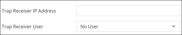
For the Trap Receiver IP Address, enter an IPv4 address to send all the Trap Community messages from all SNMP devices on the network.
The Trap Receiver User has access to the Trap Community messages.
ACLs
Access Command Lists (ACLs) are commonly used to block undesired port uses, like Remote Desktop (RDP). They can also be used to allow a printer across VLANs while restricting access to the rest of the VLAN or to restrict access to specific websites.
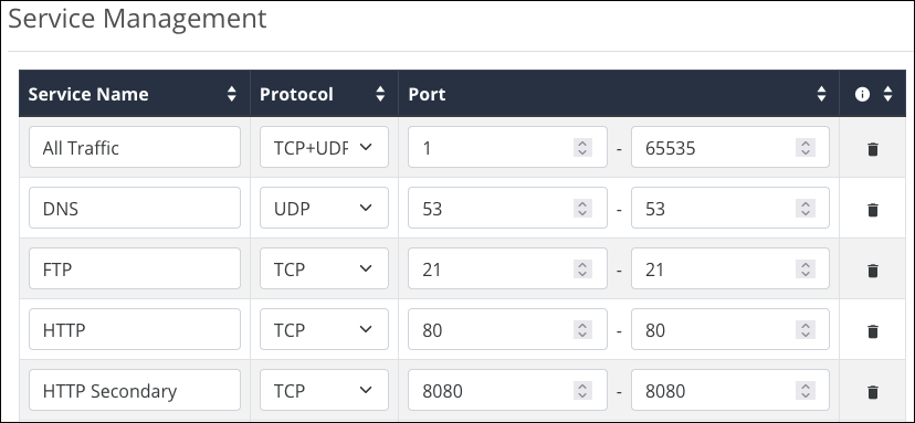
Service Management
The router comes with a list of common services, including the protocol(s) and port range they typically use. These services are selectable when creating ACL rules.
|
Service Name |
Protocol |
Port |
|---|---|---|
|
All Traffic |
TCP+UDP |
1-65535 |
|
DNS |
UDP |
53-53 |
|
FTP |
TCP |
21-21 |
|
HTTP |
TCP |
80-80 |
|
HTTP Secondary |
TCP |
8080-8080 |
|
HTTPS |
TCP |
443-443 |
|
HTTPS Secondary |
TCP |
8443-8443 |
|
TFTP |
UDP |
69-69 |
|
IMAP |
TCP |
143-143 |
|
NNTP |
TCP |
119-119 |
|
POP3 |
TCP |
110-110 |
|
SNMP |
UDP |
161-161 |
|
SMTP |
TCP |
25-25 |
|
TELNET |
TCP |
23-23 |
|
TELNET Secondary |
TCP |
8023-8023 |
|
TELNET SSL |
TCP |
992-992 |
|
DHCP |
UDP |
67-67 |
|
L2TP |
UDP |
1701-1701 |
|
PPTP |
TCP |
1723-1723 |
|
IPSec |
UDP |
500-500 |
Service Names have a maximum of 32 characters and accept alphanumeric (a - z and A - Z) characters, hyphens ( - ), underscores ( _ ), !, @, #, $, %, ^, &, *, (,), ?, +, and periods.
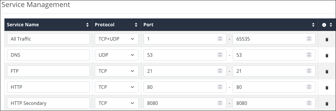
Click Add Service if you don’t see the service you’d like to create an ACL for. Click the trashcan icon to delete a service from the table.
Access Control List Settings
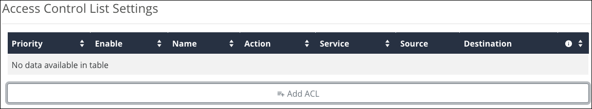
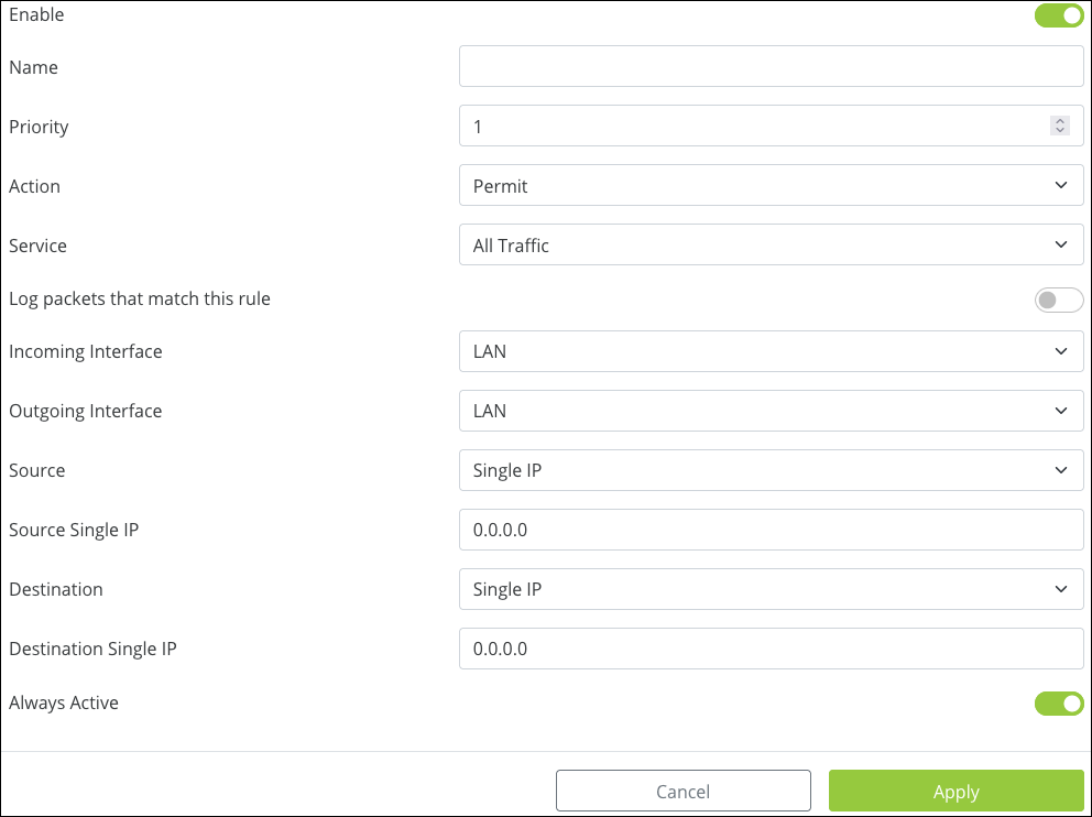
Click Add ACL to create a new rule and configure the below settings:
-
Enable – Toggle the rule on or off.
-
Name – Enter a name to identify the rule, with a maximum of 63 characters. This field accepts alphanumeric (a - z and A - Z) characters, hyphens ( - ), underscores ( _ ), !, @, #, $, %, ^, &, *, (,), ?, +, and periods.
-
Priority – Select the priority of the rule. The rules are enforced in order, meaning Priority 1 takes precedence over all other rules (2, 3, 4, etc.).
-
Action – Select whether the rule should Permit or Deny traffic.
-
Service – Select a previously configured service from the Service Management table.
-
Log packets that match this rule – Enable to record activity in the system log.
-
Incoming Interface – Select a LAN or WAN port from the dropdown.
-
Outgoing Interface – Select a LAN or WAN port from the dropdown.
-
Source – Enter a Single IP, IP Range, or MAC address of the originating device(s).
-
Destination – Enter a Single IP or IP Range of the receiving device(s).
-
Always Active – Leave enabled if the rule should always be active. Toggle it off to create a schedule for the rule.
QoS
Quality of Service (QoS) is a protocol that optimizes traffic across the network by tagging packets and giving them priority based on policy. This is an advanced feature that rarely needs to be implemented except in large, congested networks that require prioritization of network services.
DSCP is used at the Layer 3 (Network) IP level and should be used on a managed network. Consult the manufacturers of all participating network devices to ensure proper configuration.
Caution: QoS can cause network performance and reliability issues when configured incorrectly.
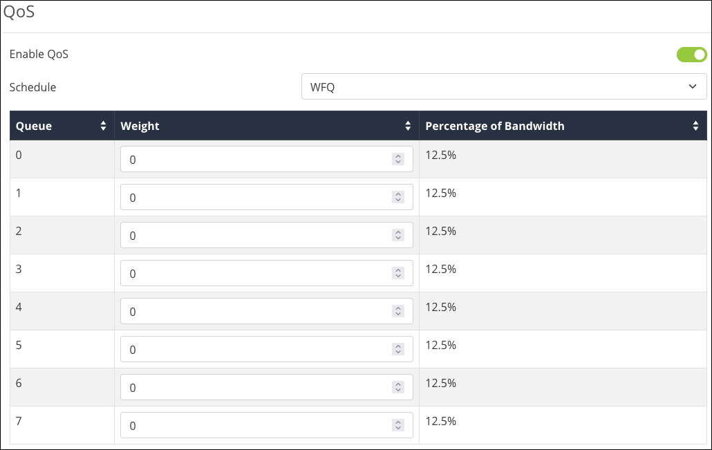
Click to Enable QoS and select a Schedule. Options include:
-
SP – Strict Priority.
-
WFQ – Weighted Fair Queuing. When selected, you must assign a Weight to each Queue number. The router calculates the Percentage of Bandwidth as you determine an appropriate weight value. The Queue runs from 0 (minimal) to 7 (very high). Weight runs from 0 (minimal) to 15 (very high).
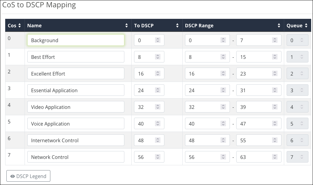
CoS to DSCP Mapping
Class of Service (CoS) monitors the types of traffic on a network and assigns priority based on that.
Use this table to map CoS values to Differentiated Services Code Pointes (DSCP) values and ranges and an associated Queue.
Click the DSCP Legend button for a reference of policy classifications for implementation on the network.
The Name field has a maximum of 63 characters and accepts alphanumeric characters (a - z and A - Z), spaces, hyphens ( - ), underscores ( _ ), !, @, #, $, %, ^, &, *, (,), ?, +, and periods.
Bandwidth Control
Bandwidth Control allows you to manage WAN interface bandwidth for specific network clients based on their IP addresses, using upstream or downstream traffic limits.
Rules can be “stacked” to further segment the use of bandwidth.
Caution: Bandwidth control can cause network performance and reliability issues when configured incorrectly.
Enable Bandwidth Control to configure rules and apply them. Disable the feature to turn off all the configured rules.
Before You Begin
-
Calculate the bandwidth requirements for all Bandwidth Control rules and make sure that the remaining bandwidth is sufficient for unregulated clients.
-
Reserve no more than 80% of the available bandwidth from the ISP in the rules you create. This guarantees available bandwidth for the IP addresses not included.
Service Management
The Service Management table shows commonly used services, their protocol(s), and port range. These services are selectable when creating Bandwidth Control rules.
Click Add Service, at the bottom of the table, to add more services. Service Names have a maximum of 32 characters and accept alphanumeric (a - z and A - Z) characters, hyphens ( - ), underscores ( _ ), !, @, #, $, %, ^, &, *, (,), ?, +, and periods.
Click the trashcan icon to delete a service.
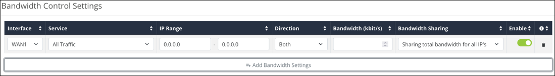
Bandwidth Control Settings
Click Add Bandwidth Settings to create a new rule.
-
Interface – Select a WAN port to apply the rule to.
-
Service – Select one of the previously configured services from the Service Table.
-
IP Range – Enter the IP address range to apply the rule to.
-
Direction – Select whether the rule affects upstream or downstream traffic.
-
Bandwidth (kbit/s) – The number of kilobits per second to allot for the bandwidth rule.
-
Bandwidth Sharing – Select Sharing total bandwidth for all IP’s to split the specified bandwidth among the clients, or Assign for each IP to allow the full specified bandwidth for each IP address.
-
Enable – Toggle the rule on or off.
Click the trashcan icon to delete a rule.
Example configuration
You have a client with a guest network, but they do not want guests using all their bandwidth downloading movies or games. Bandwidth control can be used to limit the amount of bandwidth the guest network can use.
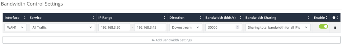
The configuration above has the IP Range of the Guest network entered and the Service is set to All Traffic. The Direction is set to Both, and the Bandwidth has been set to 30,000kbits. Enough for a few guests to stream content and browse the internet.
Bandwidth Sharing is set to Sharing total bandwidth for all IPs so that each guest is not allotted the full 30,000kbits.