Settings
System
Use this page to update the general configuration of the switch. Below are the configurable settings and best practices.
Click the Apply button at the top of the page to save changes.
Edit Password
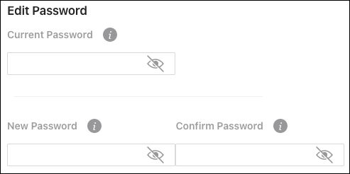
Pro Tip: Strong passwords are long and unrelated to the client’s public details. For example, thepepperonipizzas is stronger and easier to remember than P@ssword or thesmiths.
Edit Username

There is only one configurable user for switch access. The username should be unique and standardized across all devices.
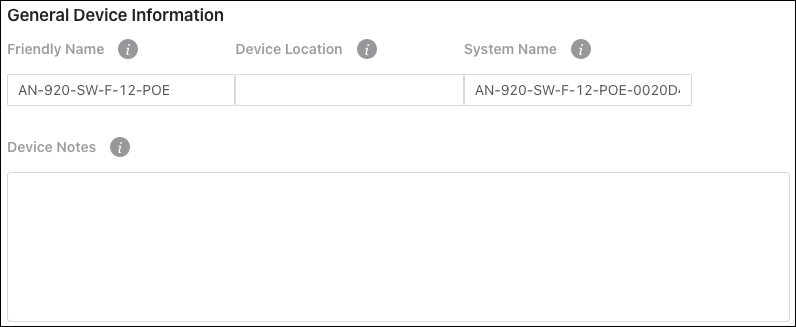
General Device Information
-
Friendly Name — Give a name that makes the switch easily identifiable. Such as “Core Switch - Rack.”
-
Device Location — Enter where the switch is located.
-
System Name — This is the name that the switch appears under during network scans by other applications. This name should be unique to the switch.
-
Device Notes — Enter additional configuration notes that wouldn’t be displayed on the Status > System page. Such as what a VLAN is being used for on this switch.
Pro Tip: If you’re using OvrC, these notes should be entered there as well.
LEDs
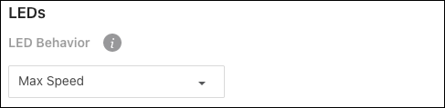
This setting determines the behavior of the 10G/PoE LED on the front of the switch.
Options include:
-
Max Speed — Illuminates if the connection to the device is at the maximum possible speed.
-
PoE — Illuminates if the switch is providing power to the connected device.
-
Disabled — Turns the LED off.
Pro Tip: The LED Behavior should be standardized across all switch installations. Be sure to leave notes about the LED Behavior If it’s not standardized.
Adjust Time Zone

Configure the Time Zone that the switch is physically installed under.
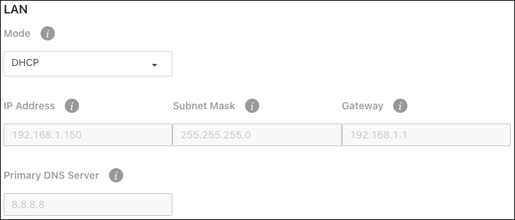
LAN
Pro Tip: Leave the switch as DHCP and make a MAC or IP reservation in the router.
Use the Mode drop-down to set the switch to a Static IP address.
Service Port
These settings allow you to change the IP address of the 920 switch’s Service Port. Use the Service Port to access the switch’s local user interface if you can no longer reach it from the LAN.
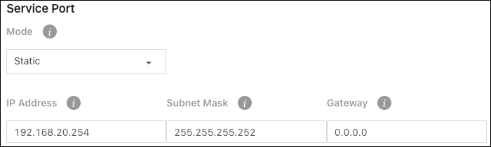
The default settings are:
-
IP Address — 192.168.20.254
-
Subnet Mask — 255.255.255.252
-
Gateway — 0.0.0.0
Pro Tip: If you change these settings make sure you notate them in a secure and easy-to-remember location. Like OvrC Notes.
Ports
Port Summary
Use this page to quickly edit port settings.
Note: EEE (Energy Efficient Ethernet) is turned off by default and cannot be turned on via local UI.
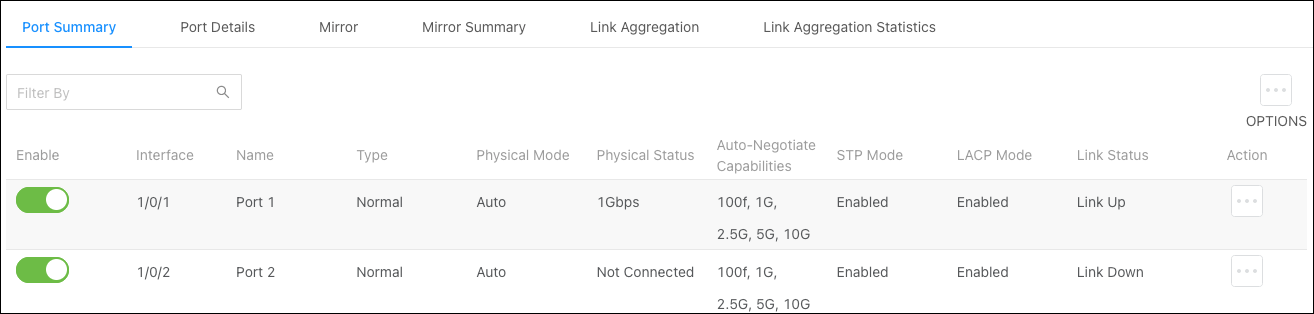
Click the Enable toggle to enable or disable a port.
Use the Options ( ) button to select multiple ports for configuration or the Action button to edit an individual port. Configurable settings appear in the Edit Port Configuration window.
Click the Apply button at the top of the page to save changes.
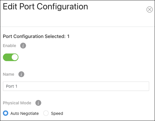
Configurable settings include:
-
Enable — Toggle to allow traffic to pass through the port. Disable the port to prevent someone from plugging additional devices into the switch or to troubleshoot potential issues with a connected device.
-
Name — Enter an easily identifiable name for the device connected to the port.
-
Physical Mode — Configure the port speed and duplex mode.
-
Auto Negotiate — Advertises the duplex mode and speed for an auto-negotiation process with the device connected to the port. Click the “x” on the speed and duplex modes you do not want the switch to advertise.
-
Speed — Select speed to force the port to 100 Mbps half or full duplex.
-
-
STP Mode — Toggle to enable or disable STP on the port.
-
LACP Mode — Toggle to enable or disable LACP on the port.
-
LACP Interface Mode — Configures the interface action when LACP is enabled and the interface is added to a Link Aggregation Group (LAG).
-
Active — The interface always attempts to negotiate an LACP connection by sending the LACPDU frames.
-
Passive — The interface waits to see a LACPDU frame.
-
-
Link Trap — Toggle to enable or disable the port from broadcasting if it has a connection or not.
-
MTU (Maximum Transmission Unit) — Enter the value for the largest possible packet size, in bytes, that a port can transmit.
-
Broadcast Storm Recovery Level — Enable to limit the amount of broadcast frames accepted and forwarded by the port by percentage, BPS (bits per second), or PPS (packets per second).
-
Multicast Storm Recovery Level — Enable to limit the amount of multicast frames accepted and forwarded by the port by percentage, BPS (bits per second), or PPS (packets per second).
-
Unicast Storm Recovery Level — Enable to limit the amount of unicast frames accepted and forwarded by the switch by percentage, BPS (bits per second), or PPS (packets per second).
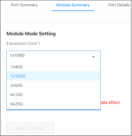
Module Summary
Note: This tab is only available if a module is detected in an expansion card slot.
The AN-920 switch can detect the type of expansion module installed. Use the drop-downs for each card to set the module configuration.
Options for the AN-SFP-100G-1 module:
-
1x100G (default)
-
1x40G
-
2x50G
-
4x10G
-
4x25G
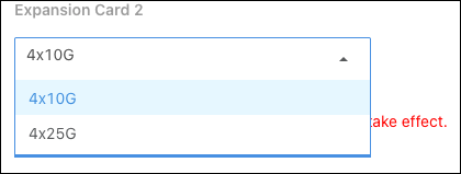
Options for the AN-SFP-25G-4:
-
4x10G (default)
-
4x25G
Note: 1x100G modules can be configured as 2 or 4x by using breakout cables.
Click Apply & Restart after making changes.
Port Details
Use this page to quickly view port information such as Physical Address, Port List Bit Offset, and the Interface Index. Use the Options () button to refresh the page.
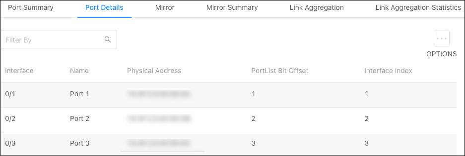
Note: The physical address is the MAC address for the individual port.
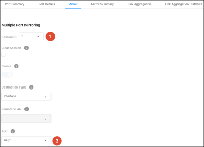
Mirror
Use port mirroring to mimic the traffic flowing through one port to another. Port mirroring is typically used to capture a recording of network traffic for troubleshooting purposes.
To configure port mirroring:
-
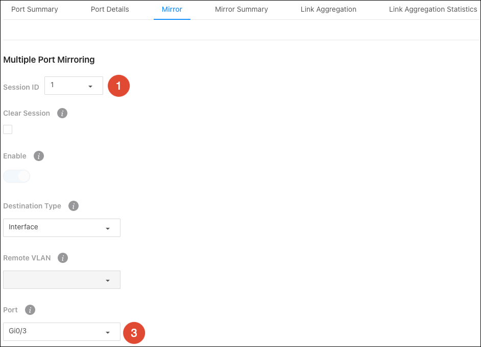
Select a Session ID. You cannot have multiple sessions with the same ID. If you have no current port mirroring sessions, use Session ID 1.
Note: You do not have to click Enable. This toggle is automatically enabled after you save the session settings.
-
Select a Destination Type. This is typically Interface.
-
Enter the Port number to receive transmit/receive data from the Source Ports. For example, if port 3 has a PC running Wireshark for packet capture, enter 3 in the Port field.
-
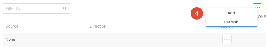
Click the Options (
) button and select Add to select the port(s) you want to mirror.
-
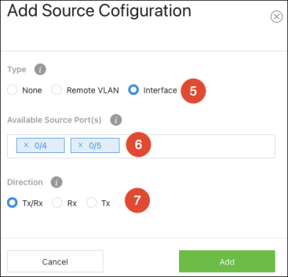
In the new window, select Interface as the Type.
-
Use the Available Source Port(s) dropdown to select the port(s) to mirror.
-
For Direction, select whether you want to mirror the packets being received (Rx), transmitted (Tx), or both (Tx/Rx), then click Add.
-
Click Apply at the top of the page. After the page refreshes Enable will be toggled on.

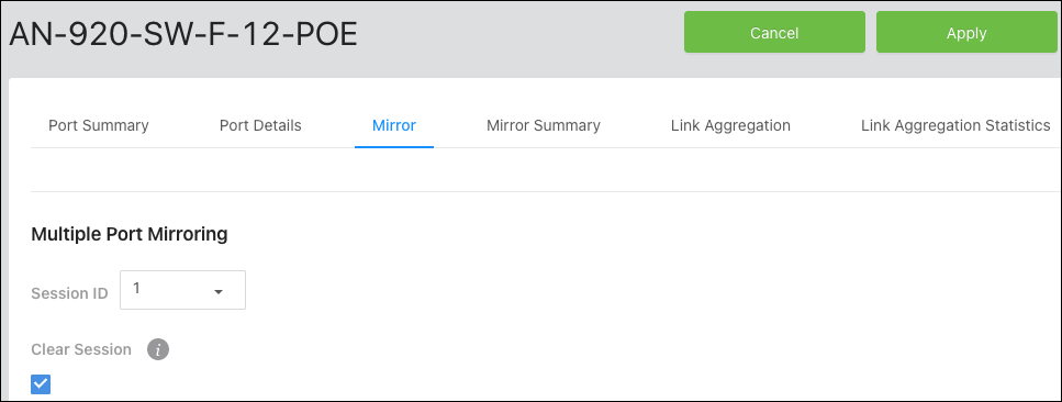
To disable a port mirroring session:
Select the Session ID you wish to end and click the Clear Session checkbox. Then click Apply at the top of the page.
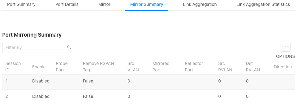
Mirror Summary
Use this page to view configured port mirroring sessions. Use the Options () button to refresh the page.
Link Aggregation
Use Link Aggregation Groups (LAG) to combine the throughput of multiple ports.
To configure a LAG:
-
Click the Options (
) button to select multiple LAGs or use the Action button to configure a single LAG. -
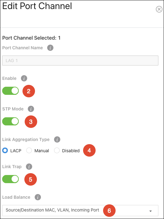
Verify Enabled is toggled on.
-
Enable or disable STP based on the networking needs.
-
Select a Link Aggregation Type. LACP is recommended.
-
LACP (Link Aggregation Control Protocol) broadcasts that the connection type is a LAG to the switch you’re connecting to for automatic configuration.
-
Manualrequires manual LAG configuration on the switch you’re connecting to.
-
Enable or disable Link Trap based on the network’s needs.
-
Leave Load Balance at the default (Source/Destination MAC, VLAN, Incoming Port), unless you have specific requirements.
Note: The selections are the information the switch uses to determine how to load balance the throughput of the LAG.
-
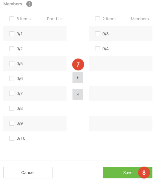
Adjust the members of the port channel (ports 3 and 4 used in the example). Use the checkboxes to select a port and the directional arrows to add/remove ports.

-
Click Save to close the window, then Apply.
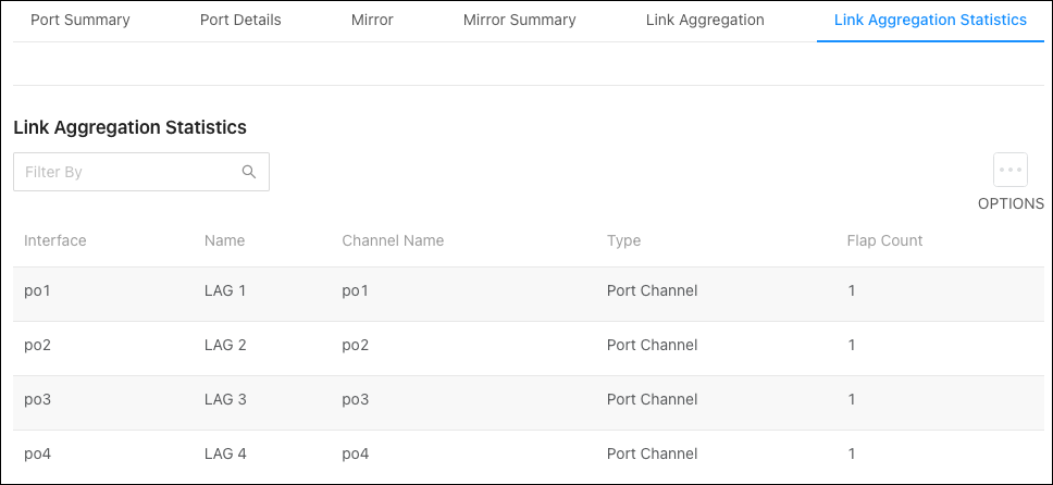
Link Aggregation Statistics
Use this page to view information about configured LAGs. Use the Options () button to refresh the page.
VLANs
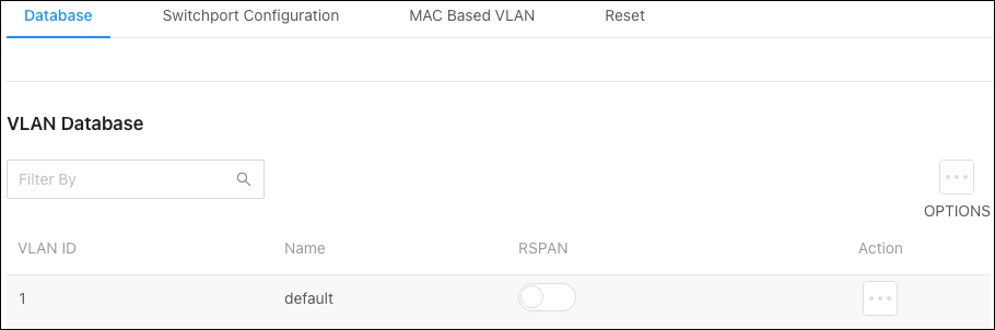
Database
Use this page to add and view VLANs that have been configured on the switch, and to enable or disable Remote Switched Port Analyzer (RSPAN).
Note: VLANs must still be applied to ports on the VLANs >Switchport Configuration page.
RSPAN allows you to mirror traffic from multiple source ports (or from all ports that are members of a VLAN) from different network devices and send the mirrored traffic to a destination port (a probe port connected to a network analyzer) on a remote device. The mirrored traffic is tagged with the RSPAN VLAN ID and transmitted over trunk ports in the RSPAN VLAN.
You can use the RSPAN toggle to enable or disable the feature or use the Options button to select multiple VLANs to enable RSPAN on.
Use the Actions () button to select an individual VLAN and give it a meaningful Name.
Use the Options () button to add a new VLAND ID to the switch.
Note: Configure the VLAN in the router before configuring the VLAN in the switch.
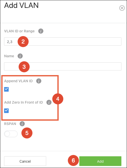
To add a VLAN(s) to the switch:
-
Click the Options (
) button, then click Add. -
Enter the VLAN ID, within the range of 2-4093. Use "-" between numbers to indicate a range. Use "," to enter multiple VLAN IDs not adjacent to each other.
-
You can a meaningful Name for the VLAN or leave the field blank.
-
Append and/or Add Zeros in front of the VLAN ID. This allows the switch to quickly create identifiers if you’re adding multiple VLANs at once.
-
Append VLAN ID - Checking this appends the VLAN ID after the name. For example, VLAN -> VLAN2.
-
Add Zero in Front of ID - Checking this adds zeroes in front of the VLAN ID, up to a total of 4 digits. For example, VLAN2 -> VLAN0002, VLAN123 -> VLAN0123. This only works when Append VLAN ID is selected.
-
Enable RSPAN, if desired.
-
Click Add, then Apply at the top of the page.

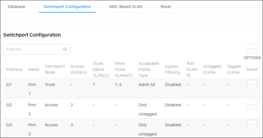
Switchport Configuration
Use this page to quickly view and configure VLANs on specific ports. Use the Options () button to modify multiple ports at once, or the Action button to edit a specific port.
Note: VLAN IDs must be configured on the VLANs > Database page.
Simple configuration
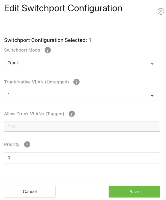
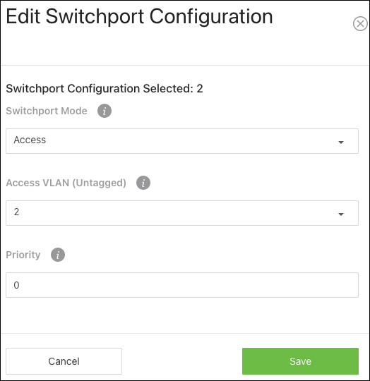
To quickly configure a port(s) for VLANs, set the Switchport Mode to Trunk or Access.
Selecting Trunk automatically allows all the VLAN IDs configured in the switch to pass through the port. Connections to other switches are typically trunk ports.
Selecting Access requires you to select a single VLAN ID as the Access VLAN (Untagged). This means that only packets tagged with the selected VLAN ID can pass through this switchport.
Complex configuration
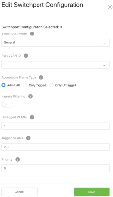
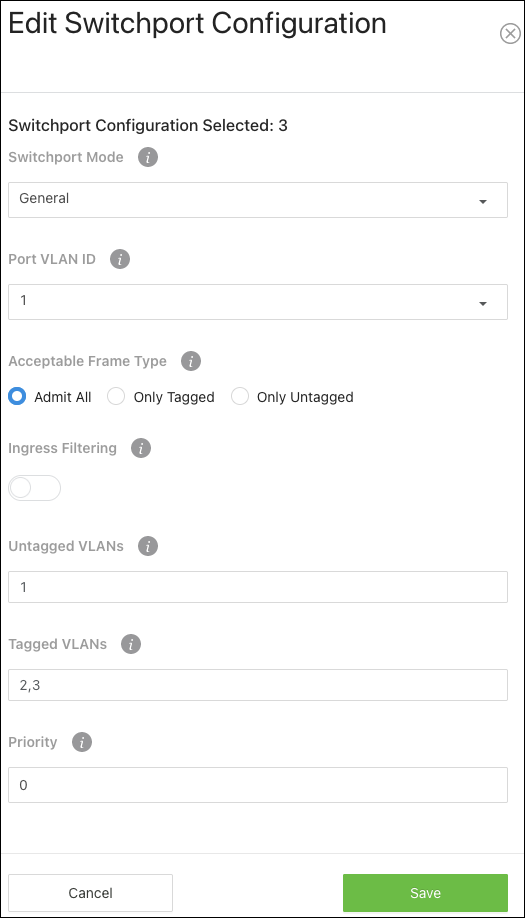
If the port must pass multiple VLANs but not all, select General as the switchport mode.
Configurable settings include:
-
Port VLAN ID (PVID) — Select the VLAN ID assigned to untagged, or priority tagged frames received on this port.
-
Acceptable Frame Type — Tell the port how to handle traffic with tagged frames. All tagged VLAN frames are forwarded in accordance with the IEEE 802.1Q VLAN standard. Options include:
-
Admit All — The port accepts priority tagged and untagged frames and assigns them the value of the PVID assigned to the interface.
-
Only Tagged — The port discards any untagged or priority tagged frames it receives.
-
Only Untagged — The port discards any tagged frames it receives.
-
-
Ingress Filtering — Enable to discard tagged frames that aren’t members of the VLAN ID assigned to the port. Leave this feature disabled to accept all tagged frames.
-
Untagged VLANs — Enter a VLAN ID in the range 1 to 4093. Use '-' to specify a range and ',' to separate VLAN IDs or VLAN ranges in the list.
-
Tagged VLANs — Enter a VLAN ID in the range 1 to 4093. Use '-' to specify a range and ',' to separate VLAN IDs or VLAN ranges in the list.
-
Priority — The default 802.1p priority assigned to untagged packets arriving at the interface. 802.1p is a Quality of Service (QoS) value used to differentiate traffic.
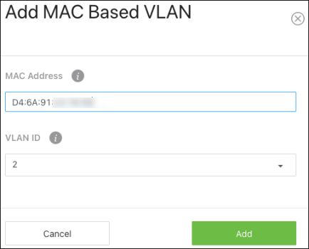
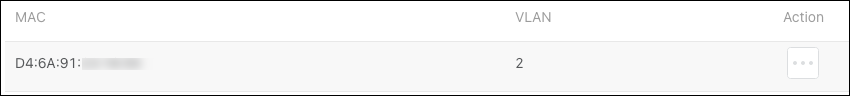
MAC Based VLAN
Use this page to bind traffic from a MAC address to a VLAN ID.
To configure a MAC based VLAN:
-
Click the Options (
) button, then Add. -
Enter the MAC address you wish to bind to a VLAN ID, then select the VLAN ID to bind it to. Click Add.
-
The MAC Based VLAN appears at the bottom of the page.


PoE
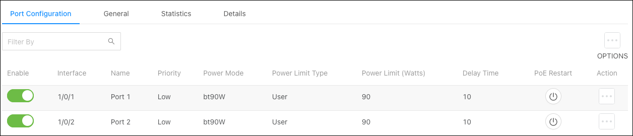
Port Configuration
Use this page to quickly enable, disable, or restart PoE on ports and view the PoE configuration on each port.
Use the Options () button to select multiple ports for configuration or the Action button to edit an individual port.
Configurable settings include:
-
Enable — Toggle to enable/disable PoE on the port.
-
Priority — Set a priority level for PoE power allocation. Higher priority levels should be reserved for devices that are critical for the system to operate, such as access points.
-
Power Mode — Set the PoE power standard for the port. Selecting a PoE class supports the PoE+ power standard, which provides up to 90W of power. Legacy supports 12.95W – 30W of power. Supported power modes include:
-
bt90W (default)
-
bt60W
-
at30W
-
af15W
-
Legacy
-
-
Power Limit Type — Select the type of power limiting for the port. Options include:
-
Class (default) — Follows the negotiated PoE class limitations.
-
User — Follows the Power Limit (Watts) setting.
-
None — No power limit.
-
-
Power Limit (Watts) — Enter the maximum amount of watts that the port can support. This field only works when the Power Limit Type is set to User.
-
Detection Type— Select a detection protocol for the port to use. Options include:
-
4Pt-Dot3af (default)
-
4Pt-Dot3af+Legacy
-
Legacy
-
-
Timer Schedule —The only option is None.
-
Delay Time (secs) — The amount of time (in seconds) before power is applied to the port after the switch starts up.
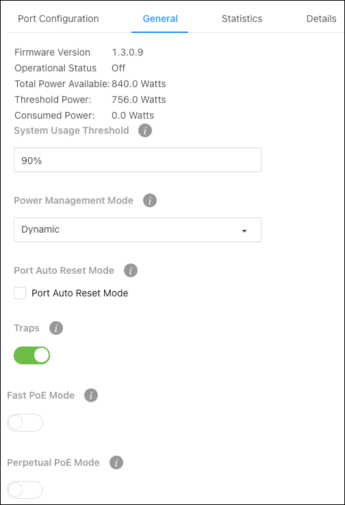
General
Use this page to configure global PoE settings for the switch. The top of the page displays PoE totals.
Configurable features include:
-
System Usage Threshold — Enter the total percentage of the switch’s usable PoE budget. For example, setting the threshold to 90% means that only 90% of the switch’s total PoE budget can be used. This prevents the switch from being overloaded.
-
Power Management Mode — Select the method that the switch determines PoE. By default, the switch decides PoE power dynamically, but you can set it to static. Doing so requires manual wattage entry on the Port Configuration page.
-
Port Auto Reset Mode — Enable or disable the ability for the switch to automatically reset a port.
-
Traps — Enable to allow the switch to send alerts about PoE statuses, such as PoE being enabled or disabled on a port.
-
Fast PoE Mode — Enable Fast PoE for the switch to provide PoE power before the boot process completes.
-
Perpetual PoE Mode — Enable to allow the switch to continue providing PoE power if the switch is restarting.
Statistics
Use this page to view PoE error counts when troubleshooting potential PoE issues.
Note: An error on the switch confirms there is a PoE issue, but it does not mean the issue is caused by the switch. Troubleshoot the connected device and Ethernet cable.
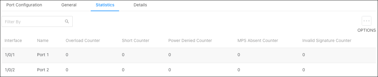
Counter explanations:
-
Overload Counter — The number of times there has been a power overload.
-
Short Counter — The number of times there has been a short-circuit condition.
-
Power Denied Counter — The number of times the connected device has been denied power.
-
MPS Absent Counter — The number of times power has stopped because the powered device couldn’t be detected.
-
Invalid Signature Counter — The number of times an invalid signature was received.
Signature detection is used to detect the presence of a powered device, where a resistance value on the connected device is expected to be found within a particular range.
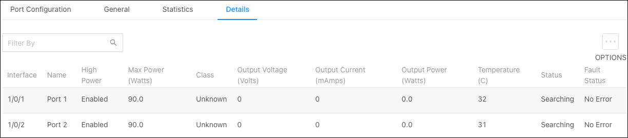
Details
Use the details page to gather information about the PoE status of each port. Click Options(), then Refresh to update the page.