Advanced
System
Management Access
System Connectivity
Use the System Connectivity page to quickly manage connections to the switch. More defined connection settings are on the specific protocol tabs.
Configurable settings include:
-
Telnet — Enable to allow telnet connections on port 23. Enable Allow New Sessions to allow new outbound telnet sessions. Disabling new sessions does not terminate existing sessions.
-
Outbound Telnet — Enable Allow New Sessions to allow new outbound telnet sessions. Disabling new sessions does not terminate existing sessions.
-
HTTP Redirect to HTTPS — Enable to redirect HTTP logins to the HTTPS port.
-
HTTPS — Enable to require an HTTPS connection for the switch’s local interface. When enabled, you must type https:// before the IP address in your browser’s address bar.
-
SSH — Enable to allow SSH connections. You can specify the port to use and The Session Timeout, in seconds.
-
Management VLAN — Use the drop-down to select which VLAN the switch’s user interface can be accessed on.
Telnet
Use this page for more defined telnet connection settings. Changes made on this page affect the System Connectivity page.
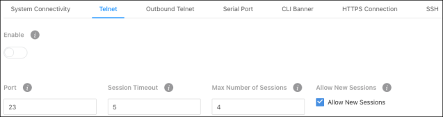
Configurable settings include:
-
Enable — Allows telnet connections on the specified port. Port 23 is the default.
-
Port — The port used to make telnet connections to the switch. 23 is the default.
Note: Changing this value does not affect current connections. New sessions must use the new value.
-
Session Timeout – The amount of time (in minutes) that the switch detects inactivity before ending the session. Configurable between 0 – 160 minutes. The default is 5.
-
Max Number of Sessions – The number of simultaneous telnet sessions (0-4) the switch allows.
-
Allow New Sessions – Enable to allow new outbound telnet sessions. Disabling new sessions does not terminate existing sessions.
Outbound Telnet
Use this page for more defined outbound telnet connection settings. Changes made on this page affect the System Connectivity page.
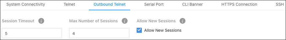
Configurable settings include:
-
Session Timeout — The amount of time (in minutes) that the switch detects inactivity before ending the session. Configurable between 0 – 160 minutes. The default is 5.
-
Max Number of Sessions — The number of simultaneous telnet sessions (0-4) the switch allows.
-
Allow New Sessions — Enable to allow new outbound telnet sessions. Disabling new sessions does not terminate existing sessions.
Serial Port
Use this page for more defined serial port connection settings. Changes made on this page affect the System Connectivity page.
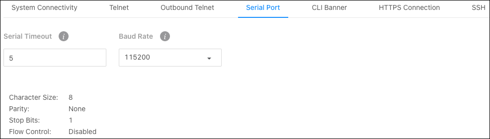
Configurable settings include:
-
Serial Timeout — The amount of time (in minutes) that the switch detects inactivity before ending the session. Configurable between 0 – 160 minutes. The default is 5.
-
Baud Rate — The number of signals per second transmitted over the physical medium, measured in bits per second.
Non-configurable connection settings:
-
Character Size: 8
-
Parity: None
-
Stop Bits: 1
-
Flow Control: Disabled
CLI Banner
Use this page to type the desired message in the text area to create the CLI (Command Line Interface) banner message.
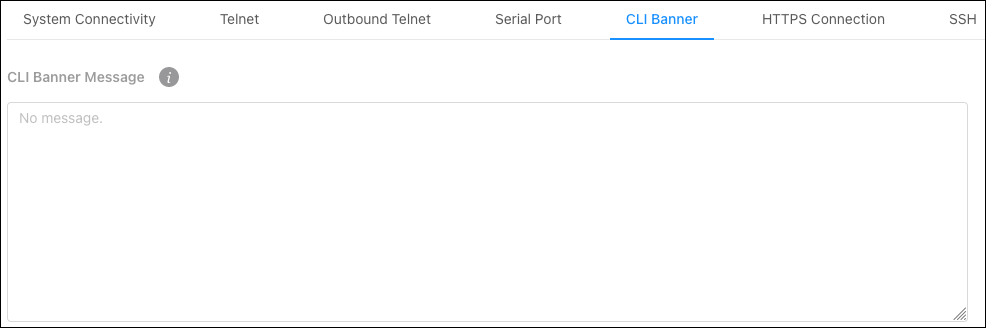
Note: If you reach the end of the line, the text wraps to the next line. The line might not wrap at the same location in the CLI. To create a line break (carriage return) in the message, press the Enter key on the keyboard. The line break in the text area will be at the same location in the banner message when viewed through the CLI.
HTTPS Connection
Use this page for more defined HTTPS connection settings. Changes made on this page affect the System Connectivity page.
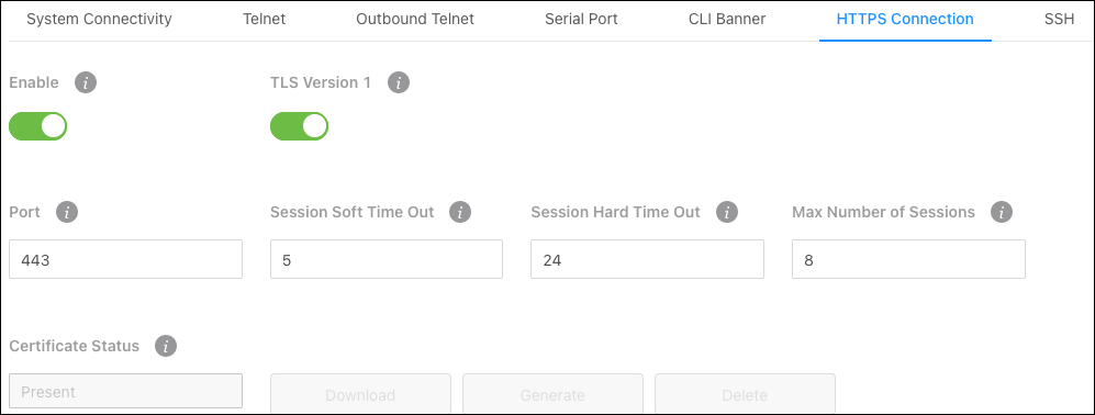
Configurable settings include:
-
Enable — Allows HTTPS connections on the specified port. Port 443 is the default.
-
TLS Version 1 — Enables or disables (TLS Transport Layer Security) Version 1.0.
-
Port — The TCP port used to make HTTPS connections to the switch. 443 is the default.
Note: Changing this value does not affect current connections. New sessions must use the new value.
-
Session Soft Time Out — The amount of time (in minutes) that the switch detects inactivity before re-checking authentication. 5 is the default.
-
Session Hard Time Out — The amount of time (in minutes) that the switch detects inactivity before ending the session. 24 is the default.
-
Max Number of Sessions – The number of simultaneous HTTPS sessions the switch allows. 8 is the default.
-
Allow New Sessions — Enable to allow new outbound telnet sessions. Disabling new sessions does not terminate existing sessions.
This page also displays the status of the SSL certificate generation process and allows you to Download, Generate, or Delete the certificate.
Certificate Status states:
-
Present — The certificate has been generated and is present on the device.
-
Absent — A certificate is not available on the device.
-
Generation In Progress — An SSL certificate is currently being generated.
SSH
Use this page for more defined SSH connection settings. Changes made on this page affect the System Connectivity page.
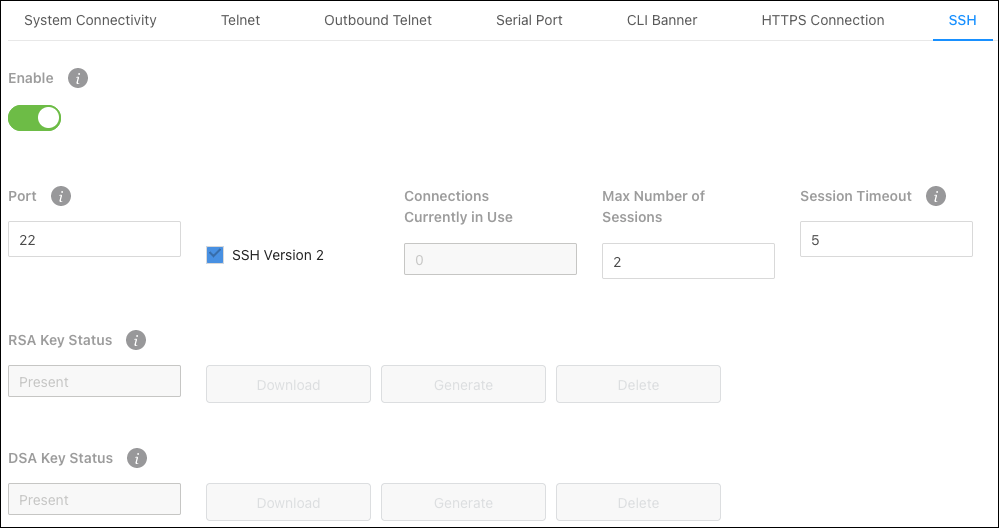
Configurable settings include:
-
Enable — Allows SSH connections on the specified port. Port 22 is the default.
-
SSH Version 2 — Enables or disables SSH version 2.
-
Port — The TCP port used to make HTTPS connections to the switch. 22 is the default.
Note: Changing this value does not affect current connections. New sessions must use the new value.
-
Max Number of Sessions — The number of simultaneous HTTPS sessions the switch allows. 8 is the default.
-
Session Timeout — The amount of time (in minutes) that the switch detects inactivity before ending the session. 5 is the default
This page also displays the status of the RSA (Rivest-Shamir-Adleman algorithm) and DSA (Digital Signature Algorithm) certificate generation process and allows you to Download, Generate, or Delete the certificate.
Certificate Status states:
-
Present – The certificate has been generated and is present on the device.
-
Absent – A certificate is not available on the device.
-
Generation In Progress – An SSL certificate is currently being generated.
SNTP
Simple Network Time Protocol (SNTP) assures the switch’s clock time is accurate to the millisecond, by synchronizing to an SNTP server.
Time sources are established by stratums, which define the accuracy of the reference clock. The higher the stratum (zero being the highest) the more accurate the clock. The switch receives time from stratum 1 and above because the switch itself is a stratum 2 device.
Examples of stratums:
-
Stratum 0 — An actual time clock, such as a GPS system, is used as the time source.
-
Stratum 1 — A server directly linked to a stratum 0 source is used. Stratum 1 time servers provide primary network time standards.
-
Stratum 2 — A time source connected to a stratum 1 server over a network. Such as stratum 2 server receiving time over the network, via NTP, from a stratum 1 server.
SNTP time definitions are determined by the following time levels:
-
T1 — The time that the original request was sent by the client.
-
T2 — The time that the original request was received by the server.
-
T3 — The time that the server sent a reply.
-
T4 — The time that the client received the server’s reply.
The switch can poll unicast and broadcast server types for the server time.
Unicast information is used for polling a server with a known IP address. SNTP servers configured on the switch are the only servers polled for synchronization information. This is the most secure method for synchronization. When selected, SNTP information is only accepted from SNTP servers defined on the SNTP Server Configuration page.
Global Configuration
Use this page to configure the Simple Network Time Protocol (SNTP) to make the switch’s clock time accurate to the millisecond.
Note: The SNTP server the switch synchronizes to is configured on the Server Configuration tab.
Configurable settings include:
-
Client Mode — Use the dropdown to determine how SNTP operates. Options include:
-
Unicast — Makes STNP operate in a point-to-point fashion. A unicast client sends a request to a designated server at its unicast address and expects a reply to determine the time, and potential round-trip delays to calculate an offset from the local time.
-
Broadcast — SNTP operates like it’s multicast but uses a local broadcast
address instead of a multicast address. The broadcast address has a single subnet scope, while a multicast address has an internet-wide scope. -
Disable — Disables the SNTP protocol on the switch.
-
-
Port — Enter a local UDP port to listen for responses and/or broadcasts. 123 is the default.
-
Unicast Poll Interval (Seconds) — Enter the number of seconds between unicast poll requests, expressed as a power of two when configured in unicast mode.
-
Broadcast Poll Interval (Seconds) — Enter the number of seconds between broadcast poll requests, expressed as a power of two when configured in broadcast mode.
-
Unicast Poll Timeout (Seconds) — Enter the number of seconds between broadcast poll requests, expressed as a power of two when configured in unicast mode. Broadcasts received prior to the expiry of the interval are discarded.
-
Unicast Poll Retry — Enter the number of times to retry a request to an SNTP server after the first time-out before attempting to use the next configured server when configured in unicast mode.
-
Number of Servers Configured — Displays the number of SNTP servers configured on the Server Configuration tab.
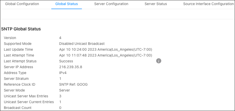
Global Status
Use this page to view the SNTP server configuration of the switch.
Server Configuration
Use this page to add SNTP servers and configure the priority of which server should be used first, and which should be used in case the servers with a higher priority cannot be contacted.
Use the Options ( ) button to refresh the page, add, or select multiple servers to configure. Use the Action button to edit or delete an existing SNTP server.
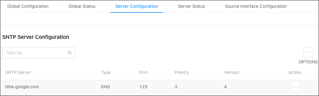
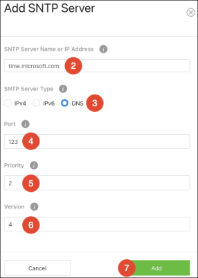
To add an SNTP server:
-
Click Options (
), then Add. -
Enter an SNTP Server Name or IP Address.
-
Select an SNTP Server Type, meaning whether it’s an IPv4, IPv6, or DNS address.
-
Enter a UDP Port the SNTP server to communicate on.
-
Enter the Priority level that the SNTP server should be used. If it’s a fallback address in case the default SNTP server fails, enter 2.
-
Enter the protocol Version number. The default is 4.
-
Click Add, then Apply at the top of the page.

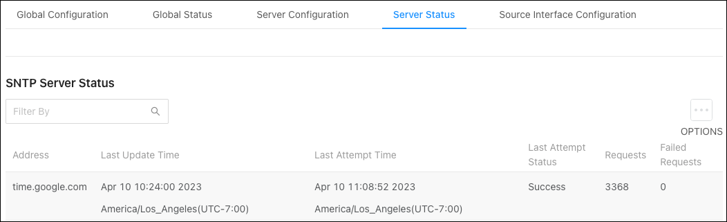
Server Status
Use this page to see the last updated time the switch has received from the configured SNTP server(s) and how many requests the switch has made to the server(s).
Click Options() > Refresh to gather the latest data.
Source Interface Configuration
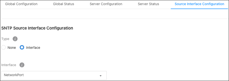
Use this page to select the Type of Interface to use as the SNTP source. Interface options include NetworkPort or ServicePort. The default Type is None.
SNMP
Simple Network Management Protocol (SNMP) provides a method for managing network devices. The Araknis 920 switch supports SNMP versions 1, 2, and 3.
SNMP Versions 1 and 2
The SNMP agent maintains a list of variables used to manage the switch, which are defined in the Management Information Base (MIB). The SNMP agent defines the MIB specification format, and the format used to access information over the network. Access rights to the SNMP agent are controlled by access strings.
SNMP Version 3
SNMP v3 adds access control and trap mechanisms. The User Security Model (USM) for SNMP v3 includes:
-
Authentication — Provides data integrity and data origin authentication.
-
Privacy — Protects against the exposure of message content by encrypting the information with Cipher-Block Chaining (CBC). Authentication and privacy is enabled on an SNMP message.
-
Timeliness — Protects against message delay and redundancy by comparing incoming messages with their time information.
-
Key Management — Defines key generation, updates, and use.
Community
Use this page to manage access rights by creating Communities for SNMP v1 and 2, or Groups for SNMP v3.
Note: Changing community names also changes the access rights.
Use the Options () button to refresh the page, add, or select multiple communities to configure. Use the Action button to edit or delete an existing community server.
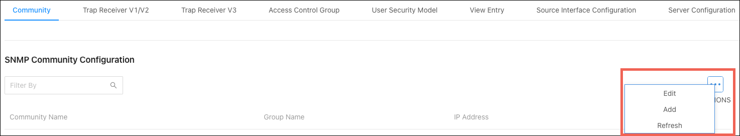
Configurable settings include:
-
Mode – Use Community for SNMPv1/2 or Group for v3.
-
Community Name — Community name used in SNMPv1/v2 packets. This is configured in the client device and determines the access the user may connect with.
-
IP Address – Enter the IP address of the device that can connect to the Community or Group.
-
Community Access – Select the permissions given to the Community or Group.
-
Community View – Enter a community view. No access is granted if this field is left empty.
Trap Receiver V1/V2
Use this page to configure the SNMP v1 or 2 trap receiver (sometimes known as a management host) that’s receiving notifications about traps generated by the switch.
Use the Options () button to refresh the page, add, or select multiple trap receivers to configure. Use the Action button to edit or delete an existing trap receiver.
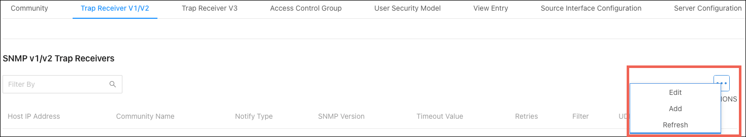
Configurable settings include:
-
Host IP Address – The IP address of the device that is going to receive the traps generated by the switch.
-
Community Name – The SNMP community name that includes the trap receiver and the SNMP agent on the switch.
-
Notify Type – Select the notification type to send to the trap receiver.
-
Trap – An SNMP message that notifies the trap receiver when a certain event has occurred on the device. The message is not acknowledged by the SNMP management host.
-
Inform – An SNMP message that notifies the trap receiver when a certain event has occurred on the device. The message is acknowledged by the SNMP management host. This type of notification is not available for SNMPv1.
-
-
SNMP Version – Select the SNMP version being used.
-
Filter – This field is optional. Enter the name of the filter configured on the trap receiver. The filter is configured using the CLI and defines which MIB objects to include or exclude from the community view.
-
UDP Port – The UDP port on the trap receiver that is receiving the SNMP notifications. The default UDP port value (162) is used if no value is specified when configuring a receiver.
Trap Receiver V3
Use this page to configure the SNMP v3 trap receiver (sometimes known as a management host) that’s receiving notifications about traps generated by the switch.
Use the Options () button to refresh the page, add, or select multiple trap receivers to configure. Use the Action button to edit or delete an existing trap receiver.
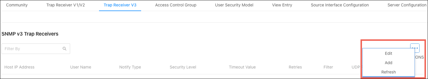
Configurable settings include:
-
Host IP Address – The IP address of the device that is going to receive the traps generated by the switch.
-
User Name – The name of the SNMP user that is authorized to receive the SNMP notification.
-
Notify Type – Select the notification type to send to the trap receiver.
-
Trap – An SNMP message that notifies the trap receiver when a certain event has occurred on the device. The message is not acknowledged by the SNMP management host.
-
Inform – An SNMP message that notifies the trap receiver when a certain event has occurred on the device. The message is acknowledged by the SNMP management host. This type of notification is not available for SNMPv1.
-
-
Security Level – Select one of the following security levels for the NSMP user:
-
No Auth No Priv – No authentication and no data encryption (no security).
-
Auth No Priv – Authentication with no data encryption. With this security level, users send SNMP messages using an MD5 key/password for authentication. It does not send a DES key/password for encryption.
-
Auth Priv – Authentication and data encryption. With this security level, users send an MD5 key/password for authentication and a DES key/password for encryption.
-
-
Filter – This field is optional. Enter the name of the filter configured on the trap receiver. The filter is configured using the CLI and defines which MIB objects to include or exclude from the community view.
-
UDP Port – The UDP port on the trap receiver that is receiving the SNMP notifications. The default UDP port value (162) is used if no value is specified when configuring a receiver.
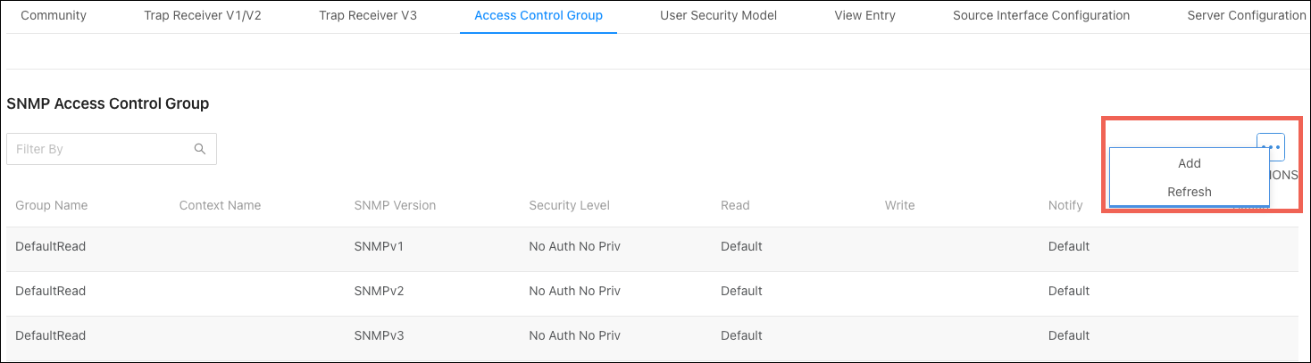
Access Control Group
Use this page to configure SNMP Access Control Groups and view a summary of all the configured groups. These SNMP groups allow network managers to assign different authorization levels and access rights to specific switch features and attributes. The switch is preconfigured with several default SNMP groups.
The SNMP community can reference an SNMP group to provide security and context for agents receiving requests, initiating traps, and management system tasks. An SNMP agent cannot respond to a request from a management system outside the group or groups it’s configured for.
Use the Options () button to refresh the page or add a new Access Control Group.
Configurable settings include:
-
Group Name – Enter an easily identifiable name for the Access Control Group.
-
SNMP Version – Select the SNMP version for the Access Control Group.
-
Security Level – Select one of the following security levels for the NSMP user:
-
No Auth No Priv – No authentication and no data encryption (no security). This is only available to SNMP v1 or 2 groups.
-
Auth No Priv – Authentication with no data encryption. With this security level, users send SNMP messages using an MD5 key/password for authentication. It does not send a DES key/password for encryption.
-
Auth Priv – Authentication and data encryption. With this security level, users send an MD5 key/password for authentication and a DES key/password for encryption.
-
-
Context Name – Enter the SNMP context associated with the SNMP group and its views. A user or a management application specifies the context name to get the performance information from the MIB objects associated with that context name. The Context EngineID identifies the SNMP entity that should process the request (the physical router), and the Context Name tells the agent in which context it should search for the objects requested by the user or the management application.
-
Group Access Rights Read – Select the level of read access rights for the group. The menu includes the available SNMP views. When adding a group.
-
Group Access Rights Write – Select the level of write access rights for the group. The menu includes the available SNMP views. When adding a group.
-
Group Access Rights Notify – Select the level of notify access rights for the group. The menu includes the available SNMP views. When adding a group.
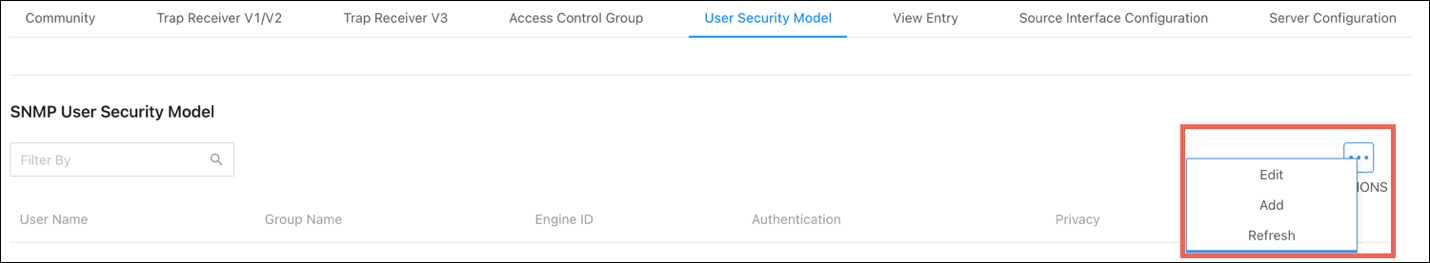
User Security Model
Use this page to configure SNMP v3 users.
Click the Options () button to refresh the page, add, or edit a new SNMP user.
Configurable settings include:
-
Engine ID Type – Select the Engine ID type being used. Local or Remote. Each SNMP v3 agent has an engine ID as a unique identifier for the device.
-
User Name – A unique identifier for the user. Leading or embedded blanks cannot be used.
-
Group Name – The SNMP group name to associate the user with.
-
Authentication Method – Select one of the following options:
-
None – No authentication is used.
-
MD5 – This protocol requires a password of 1-32 hexadecimal characters.
-
SHA – This protocol requires a password of 1-32 hexadecimal characters.
-
MD5-Key – This protocol requires a pre-generated MD5 authentication
key of 32 hexadecimal characters. -
SHA-Key – This protocol requires a pre-generated SHA authentication key of 40 hexadecimal characters.
-
View Entry
An SNMP View is a mapping between SNMP scalar and tabular objects and the access rights configured for the view. Use this page to configure access to one or more MIB OID (MIB Object Identifier) nodes for an SNMP View Name.
Note: An SNVMP View Entry must be configured for an SNMP v3 agent to work.
Click the Options () button to refresh the page or add a new View Entry.
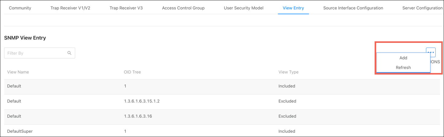
Configurable settings include:
-
View Name – Enter a unique name to identify the SNMP view.
-
View Type – Select an View Type to use. Options include:
-
Included – Grants access to the OID subtree.
-
Excluded – Denies access to the OID subtree.
-
-
OID Tree – The ASN.1 subtree to grant or deny access to.
Source Interface Configuration
Use this page to specify the physical or logical interface to use as the SNMP client source interface. When an IP address is configured on the source interface, the IP address is used in the IP header of SNMP management packets for all SNTP communications between the local SNMP client and the remote SNTP server.
This allows security devices, like firewalls, to identify incoming source packets from a specific device.
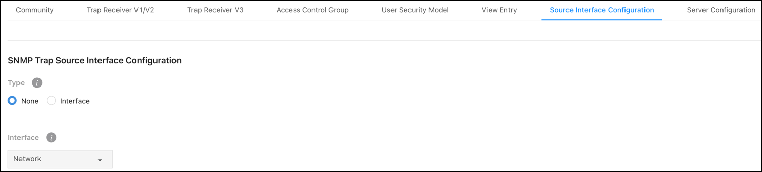
Configurable settings include:
-
Type – Select a source interface type. Options include:
-
None – The primary IP address of the origination (outbound) interface is used as the source address.
-
Interface– The primary IP address of the physical switchport is used as the source address.
-
The Interface drop-down can only be set to Network. This option includes the physical port, VLAN routing interface, and the network source IP.
Click Apply at the top of the page to save changes.
Server Configuration
Use this page to specify the UDP port number the SNMP server uses to listen for requests.
Caution: Changing this value may cause existing SNMP transactions to cease communicating with the device until the client applications are reconfigured to use the new port number.
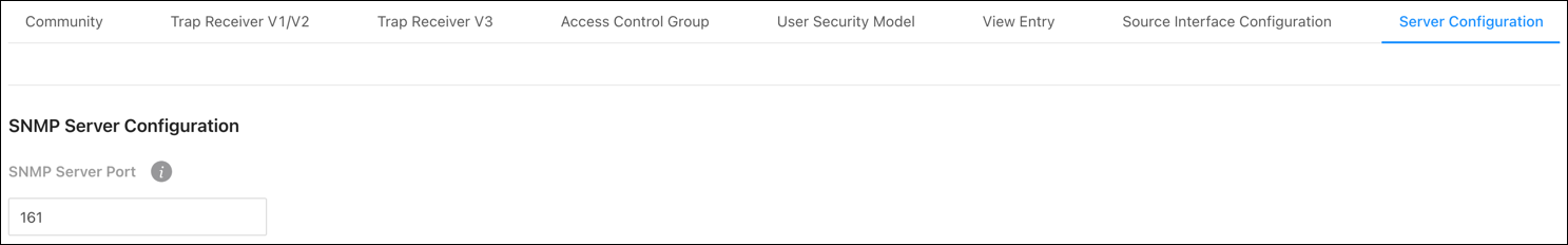
Click Apply to save changes.
Time Ranges
Use these pages to configure time ranges for Access Command Lists (ACLs). Time ranges can be set for one or more rules within an ACL using a periodic or absolute time, except for the deny all rule each ACL has.
Time ranges must have a name before they can be referenced by an ACL rule.
Configuration
Click the Options () button to add or edit a named Time Range or refresh the page. Use the Action button to delete a Time Range.
Click Enable to make Time Ranges active.
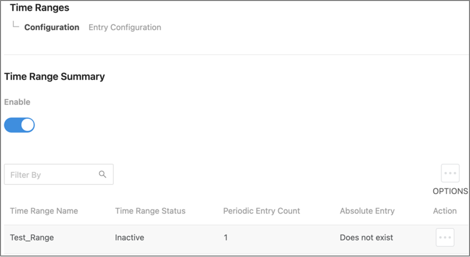
Table field descriptions:
-
Time Range Name – The unique name entered to identify the Time Range.
-
Time Range Status – Displays whether the Time Range is active.
-
Periodic Entry Count – The number of periodic time range entries currently configured with the Time Range.
-
Absolute Entry – The number of absolute time range entries currently configured with the Time Range.
Entry Configuration
Use this page to add periodic and absolute time range entries.
To add an entry, select a Time Range Name, then click the Options () button > Add.
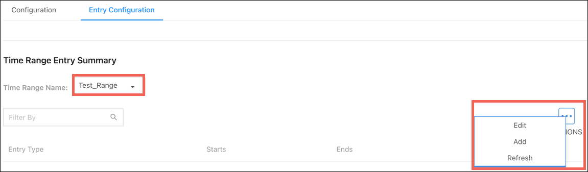
The Configurable settings depend on which Entry Type you select. The below table describes these settings.
|
Entry Type |
Field |
Description |
|---|---|---|
|
Periodic |
Start Days |
Select the day the time range entry begins. If more than one day is selected, they must match the End Days field. |
|
Starting Time of Day |
Enter the time of day the entry begins. Uses a 24-hour format. |
|
|
End Days |
The day, or days, the entry ends. If multiple days are selected, they must match the Start Days field. |
|
|
Ending Time of Day |
The time of day the entry ends. Uses a 24-hour format. |
|
|
Absolute |
Starts |
The calendar day the entry begins. |
|
Ends |
The calendar day the entry ends. |
To delete a Time Range Entry, click the Action button next to the entry.
Logs
The logs display a record of system events and can be configured to only display the most pertinent system information.
Event Log
Use this page to view system events recorded since the last restart of the switch. Refresh the page to see new events. The Options () button gives you the ability to display a specified number of rows, and to Refresh the logs.
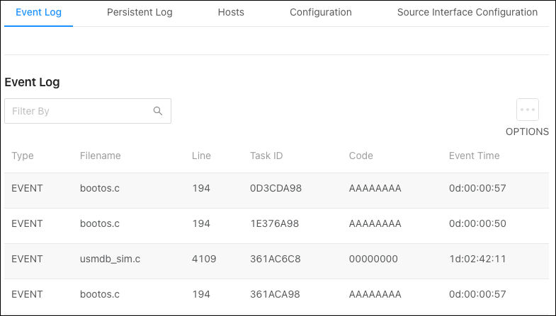
Table field descriptions:
-
Type – The incident category of the log entry. Event, Error, etc.
-
Filename – The source code file name of the event’s origin.
-
Line – The line number of the event within the source code.
-
Task ID – The system identifier of the task that was running when the event occurred.
-
Code – An event-specific code assigned to the event.
-
Event Time – A time stamp (days:hours:minutes:seconds) that indicates when the event occurred in reference to the system’s uptime.
Persistent Log
This page shows current events, and events recorded before the last system restart. Refresh the page to see new events. The Options () button gives you the ability to display a specified number of rows, and to Refresh the logs.
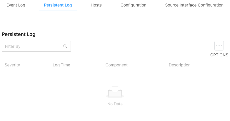
Table field descriptions:
-
Severity – The severity level of the log entry. The severity levels displayed can be configured under Advanced > System > Logs > Configuration tab.
-
Log Time – A time stamp (days:hours:minutes:seconds) that indicates when the event occurred.
-
Component – The component that issued the log entry.
-
Description – A text description of the log entry.
Hosts
Use this page to configure remote hosts for the switch to send and capture logs to. Click the Options () button to Edit, Add a new host, or Refresh the list.
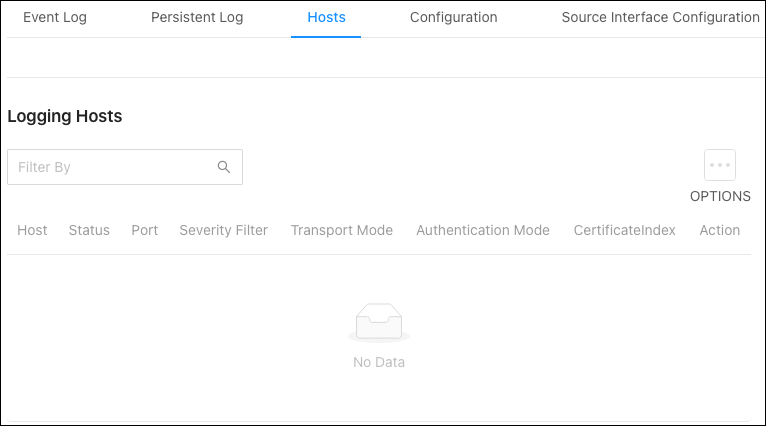
Table field descriptions:
-
Host – The IP address or DNS-resolvable host name of the remote host that is receiving log messages.
-
Status – Indicates if the host is configured to actively log or not.
-
Port – The UDP port on the logging host that the syslog messages are being sent.
-
Severity Filter – Severity level threshold for log messages, configured under Advanced > System > Logs > Configuration tab. All log messages with a severity level at and above the configured threshold are sent to the logging host.
-
Transport Mode – UDP or TLS. If TLS is not configured the default transport mode is UDP.
-
Authentication Mode – Using TLS, the security user can configure an anonymous authentication mode, where no client authentication is done by the syslog server.
Using x509/name authentication mode, two-way authentication is done by the syslog client and the syslog server. -
Certificate Index – Index used to identify corresponding certificate files.
-
Action – Edit or remove a logging host.
Configuration
Use these fields to configure the behavior and data for the switch to log.
Buffered Log Configuration:
-
Enable – Enabled by default, this feature logs data to the buffered (RAM) file.
-
Behavior – Specifies what happens when the buffered log is full.
-
Wrap: Deletes the oldest messages.
-
Stop on Full: Stops writing new messages.
-
Command Logger Configuration:
Enable or Disable logging of command-line interface (CLI) commands issued to the switch. This setting is disabled by default.
Console Log Configuration:
-
Enable – Enable or disable logging to any serial device attached to the switch.
-
Severity Filter – Sets the severity of the messages to log. All messages at or above the selected severity level are logged to the console.
Persistent Log Configuration:
-
Enable – Enable or disable logging to the persistent log. These messages are not deleted when the switch restarts.
-
Severity Filter – Sets the severity of the messages to log. All messages at or above the selected severity level are logged to the switch.
Syslog Configuration:
-
Enable – Enable or disable logging to the configured syslog hosts. When disabled, the switch does not relay logs to syslog hosts and no messages are sent to any collector/relay.
When enabled messages are sent to the collectors/relays using the values configured for each collector/relay.
-
Protocol Version – The RFC version of the syslog protocol.
-
Local UDP Port – The UDP port the switch sends syslog messages from.
Source Interface Configuration
Use this page to configure the port that the Syslog host is connected to.
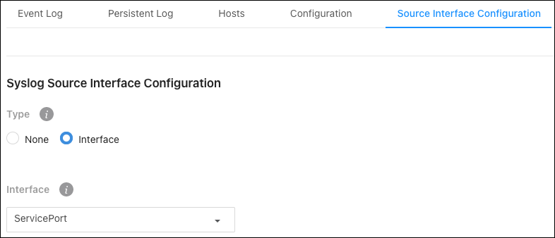
Configurable settings include:
-
Type – Select Interface to configure a Syslog Source Interface. Default is None.
-
Interface – Use the dropdown to select the type of interface to use. Service port or Network port.
System Statistics
Pages in the Statistics section contain information about the amount and types of traffic the switch is transmitting and receiving.
Switch
Use the Options () button to refresh the statics for a specific heading or click the Clear Counters button to clear all the statistics information on the page.
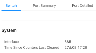
System counters descriptions:
-
Interface – The interface index object value of the interface table entry associated with the switch’s processor. Use this value to identify the interface when managing the switch with SNMP.
-
Time Since Counters Last Cleared – The amount of time in days:hours:minutes:seconds since the statistics for the switch have been reset.
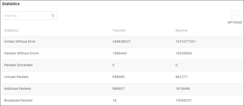
Statistics counters descriptions:
-
Octets Without Error – The total number of octets (bytes) successfully transmitted or received data by the processor. This number includes FCS octets but excludes framing bits.
-
Packets Without Errors – The total number of packets successfully transmitted or received by the processor. Includes unicast, broadcast, and multicast packets.
-
Packets Discarded – The number of packets chosen to be discarded to prevent them from being deliverable to a higher-layer protocol. Such as discarding packets to free up buffer space.
-
Unicast Packets – The number of subnetwork-unicast packets transmitted or received from a higher-layer protocol.
-
Multicast Packets – The number of packets transmitted or received being directed to a multicast address.
-
Broadcast Packets – The number of packets transmitted or received being directed to a broadcast address.
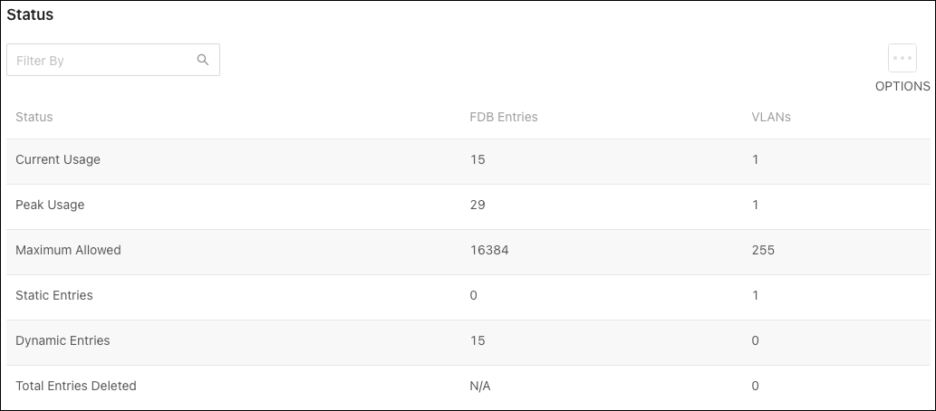
Status counters descriptions:
-
Current Usage – In the FDB entries column, the value is the number of learned and static entries in the MAC address table. In the VLANs column, the number shows the number of static and dynamic VLANs that exist in the VLAN database.
-
Peak Usage – The highest number of entries in the MAC address table or VLAN database that an admin statically configured.
-
Maximum Allowed – The maximum number of statically configured or dynamically learned entries allowed in the MAC address table or VLAN database.
-
Static Entries – The current number of statically configured entries in the MAC address table or VLAN database that an admin configured.
-
Dynamic Entries – The current number of dynamically learned entries in the MAC address table or VLAN database that an admin configured.
-
Total Entries Deleted – The number of VLANs created and deleted since the last time the switch was restarted. This field is not applicable to MAC address table entries.
Port Summary
This table shows statistics about the packets transmitted and received for individual interfaces (switchports and LAGs).
Use the Options () button to Refresh or Clear the statistics in the table.
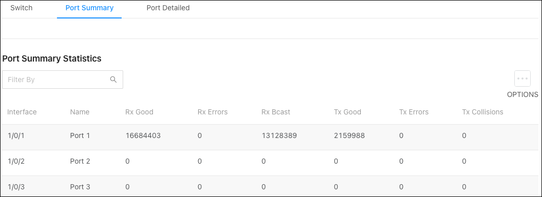
Column descriptions:
-
Interface – The interface (switchport or LAG) number.
-
Name – The name given to the interface.
-
RX Good – The total number of inbound packets received by the interface without error.
-
RX Errors – The total number of inbound packets containing errors, preventing them from being deliverable on the interface.
-
RX Bcast – The total number of inbound packets received by the interface directed to a broadcast address. This does not include multicast packets.
-
TX Good – The total number of outbound packets received by the interface without error.
-
TX Errors – The total number of outbound packets containing errors, preventing them from being deliverable on the interface.
-
TX Collisions – The best estimate of the total number of collisions on the interface.
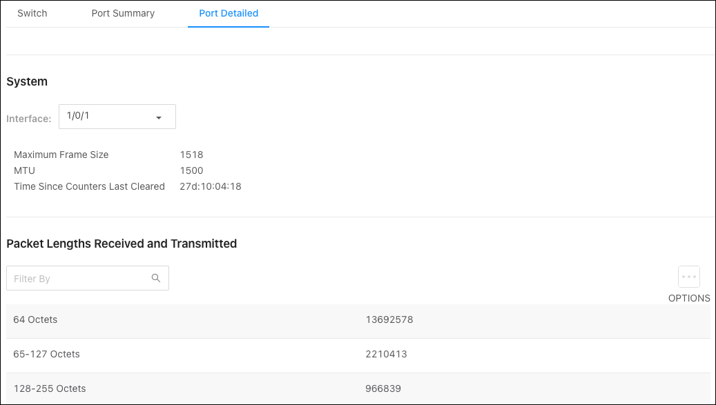
Port Detailed
This page allows you to select an interface and view detailed statistics about it, such as the Maximum Frame Size, MTU, and the Packet Lengths Received and Transmitted.
Use the Interface dropdown to select a switchport or LAG. Click the Options () button to Refresh the page for the most current statistics.
Switching
IGMP Snooping
Configuration
Use this page to enable IGMP Snooping on the switch and view related counts.
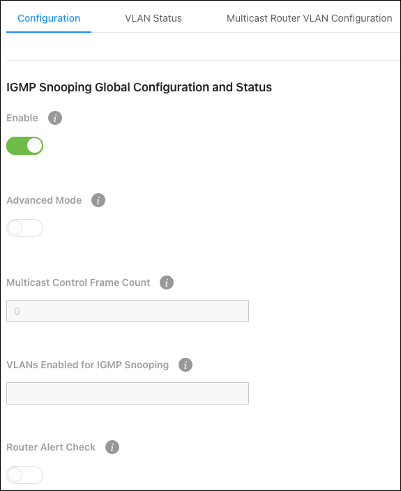
Configurable settings:
-
Enable - Enables/disables IGMP snooping on the switch.
-
Advanced Mode - Enabled Advanced mode if the IGMP environment which is likely to have large bursts of IGMP messages. The switch’s CPU has a buffer shared by all kinds of packets. When there is a burst of IGMP snooping packets, some would be dropped. To prevent this, Advanced Mode increases the buffer size for IGMP snooping packets, sacrificing the buffer size allocated for other kinds of packets. These “other” packets may be dropped.
-
Router Alert Check — Enable for the switch to inspect packets when they are being forwarded, even though the packet is not directly addressed to this switch.
Read-only fields:
-
Multicast Control Frame Count — The number of multicast frames the switch has processed.
-
VLANS Enabled for IGMP Snooping — The number of VLANs configured on the switch for IGMP snooping.
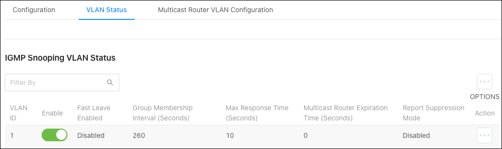
VLAN Status
Use this page to enable IGMP snooping on VLANs configured on the switch.
Click the Options () button to Refresh or Clear the statistics in the table.
Configurable settings include:
-
VLAN ID — Select a VLAN ID that’s been configured on the switch. You can only select a VLAN that hasn’t already been configured for IGMP Snooping.
-
Fast Leave — Enable to remove the multicast group specified in an IGMP Leave report without sending an IGMP query message and waiting for a response.
-
Group Membership Interval (Seconds) — The number of seconds the VLAN waits for a report for a particular multicast group on the VLAN before the IGMP snooping feature deletes the VLAN from the group.
-
Max Response Time (Seconds) — The number of seconds the VLAN waits after sending a query if it does not receive a report for a particular multicast group. The specified value should be less than the Group Membership Interval.
-
Multicast Router Expiration Timer (Seconds) — The number of seconds the VLAN waits to receive a query before it is removed from the list of VLANs with multicast routers attached.
-
Report Suppression Mode — The IGMPv1 and IGMPv2 report suppression mode. The device uses IGMP report suppression to limit the membership report traffic sent to multicast-capable routers. When this mode is enabled, the device does not send duplicate reports to the multicast router. Note that this mode is supported only when the multicast query has IGMPv1 and IGMPv2 reports. This feature is not supported when the query includes IGMPv3 reports. The options are as follows:
-
Enabled - Only the first IGMP report from all hosts for a group IGMP report is forwarded to the multicast routers.
-
Disabled — The device forwards all IGMP reports from all hosts in a multicast group to the multicast routers.
-
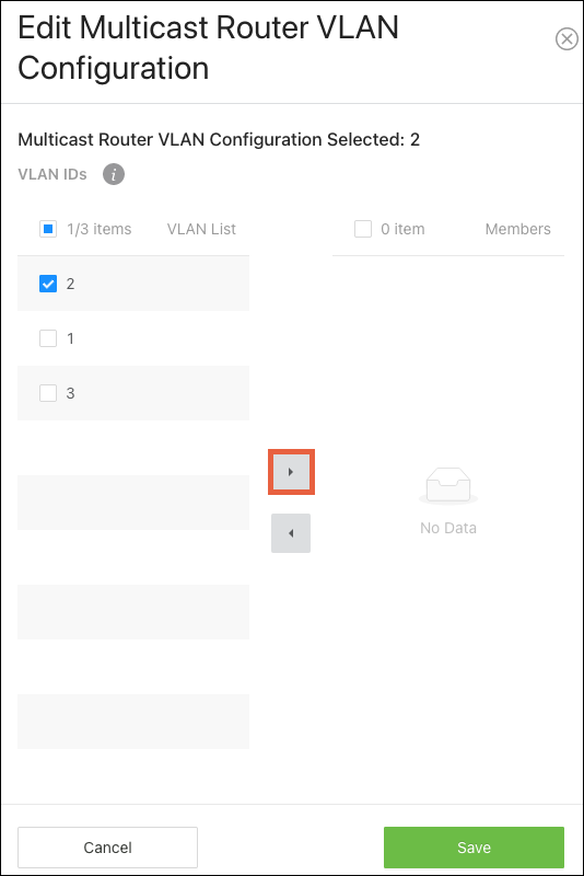
Multicast Router VLAN Configuration
Use this page to configure VLANs for multicast routing. When enabled, multicast routers learn which multicast groups are active by periodically checking with each member of the multicast group. Read Understanding Multicast & IGMP for more information about multicast groups.
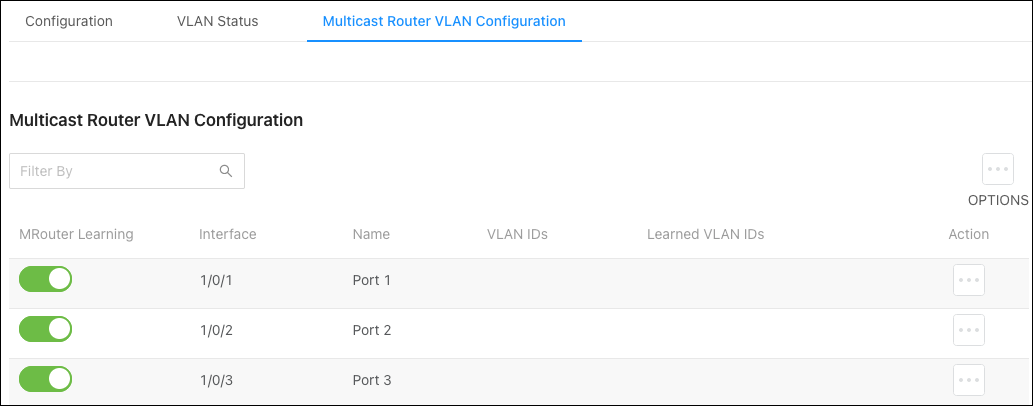
To configure multicast routing:
-
Use the Options button to configure multiple ports or the Actions button to edit a single port.
-
Select the VLAN ID(s) you want the port to act as the multicast router for, then click the right arrow to add them.
-
Click Save, then Apply at the top of the page.

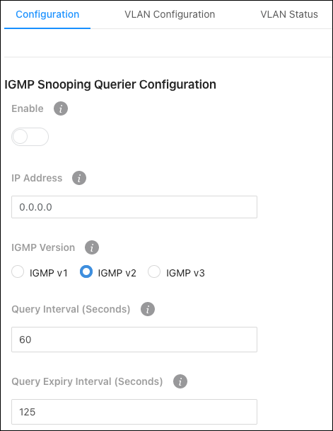
IGMP Snooping Querier
Configuration
Use this page for IGMP Snooping Querier administration.
Configurable settings include:
-
Enable - Enable to allow the switch to send periodic IGMP queries that trigger IGMP report messages from the switches that want to receive IP multicast traffic. IGMP snooping listens to these IGMP reports to establish appropriate forwarding.
-
IP Address - The address to be used as the source address in periodic IGMP queries when no IP address is configured on the VLAN on which the query is being sent.
-
IGMP Version — Select the IGMP version to use in the queries.
-
Query Interval (Seconds) — The amount of time between queries.
-
Query Expiry Interval (Seconds) — The amount of time the device remains in non-querier mode after it discovers that there is a multicast querier on the network.
VLAN Configuration
Use this page to add VLANs that the switch should act as the IGMP querier for. To learn more about IGMP queriers, read Understanding Multicast & IGMP.
Caution: Only enable IGMP Snooping Querier on the switch where your IGMP topology starts, called the core IGMP switch. This IGMP querying switch asks each device on the network which multicast traffic they want.
To add a VLAN to the switch’s IGMP snooping querier configuration:
-
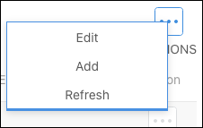
Click the Options button, then Add.
-
Select a VLAN ID.
-
Enable Querier Election Participation if the VLAN should participate in the IGMP querier Election process.
-
If desired, enter a Querier VLAN IP Address.
-
Click Add, then Apply at the top of the page.
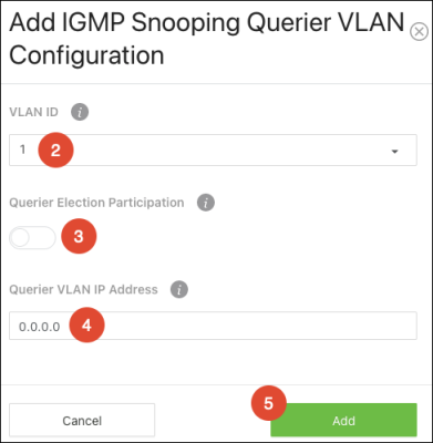
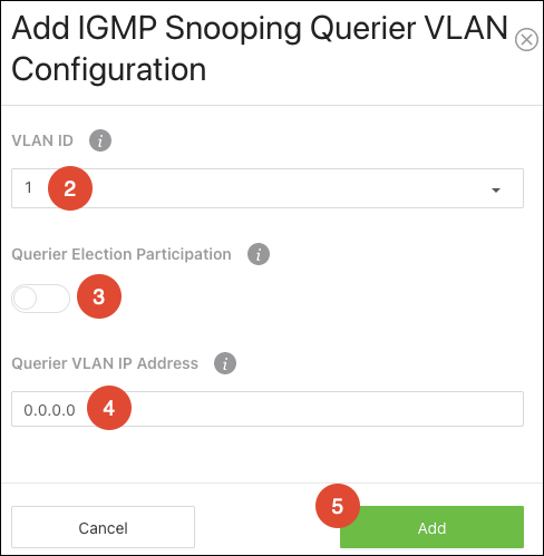
Configured VLANs are listed at the bottom of the page.
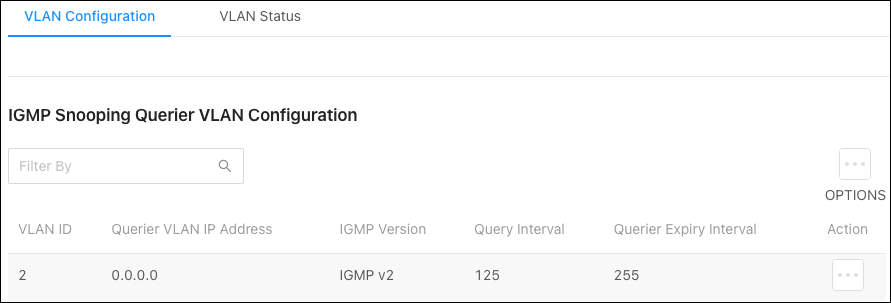
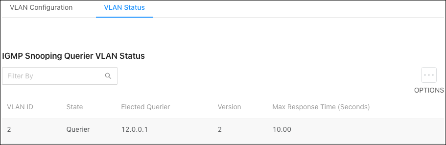
VLAN Status
Use this page to view information about the IGMP snooping querier status for all VLANs that have the snooping querier enabled.
Spanning Tree Protocol
Switch
Use this page to configure global Spanning Tree Protocol (STP) settings for the switch.
STP is a Layer 2 protocol that decides the best path for LAN traffic when multiple options exist, preventing network loops while guaranteeing redundancy in case of link failure. For more information about STP, read Understanding Spanning Tree Protocol (STP) & Best Practices.
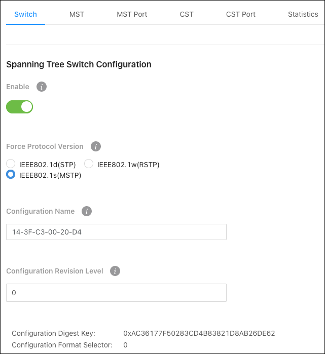
Configurable settings include:
-
Enable — Enables STP on the switch.
-
Force Protocol Version — Select the STP version for the switch to use.
-
Configuration Name — Typically left alone, you can enter the name of the MSTP region. Each switch that participates in the same MSTP region must share the same Configuration Name, Configuration Revision Level, and MST-to-VLAN mappings.
-
Configuration Revision Level — This number must be the same on all switches participating in the MSTP region.
MST
Use the MST Summary page to view the Multiple Spanning Tree Instances (MSTIs) on the device.
Multiple Spanning Tree Protocol (MSTP) allows the creation of MSTIs based upon a VLAN or groups of VLANs. Configuring MSTIs creates an active topology with a better distribution of network traffic and an increase in available bandwidth when compared to classic STP MST Port.
The Spanning Tree Maximum Hops field displays the maximum number of hops a Bridge Protocol Data Unit (BPDU) is allowed to traverse within the spanning tree region before it is discarded. The default value is 20.
MST instances appear in the table at the bottom of the page.
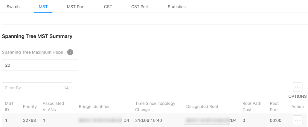
Table field descriptions:
-
MST ID — Identifies the MST instance.
-
Priority — The bridge priority for the spanning-tree instance. This value affects the likelihood that the bridge is selected as the root bridge. A lower value increases the probability that the bridge is selected as the root bridge.
-
Associated VLANs — The number of VLANs that are mapped to the MSTI. This number does not contain any information about the VLAN IDs that are mapped to the instance.
-
Bridge Identifier — A unique value that is automatically generated based on the bridge priority value of the MSTI and the base MAC address of the bridge. When electing the root bridge for an MST instance, if the bridge priorities for multiple bridges are equal, the bridge with the lowest MAC address is elected as the root bridge.
-
Time Since Topology Change — The amount of time that has passed since the topology of the MSTI changed.
-
Designated Root — The bridge identifier of the root bridge for the MST instance. The identifier is made up of the bridge priority and the base MAC address.
-
Root Path Cost — The path cost to the designated root for this MST instance. Traffic from a connected device to the root bridge takes the least-cost path to the bridge. If the value is 0, the cost is automatically calculated based on port speed.
-
Root Port — The port on the bridge with the least-cost path to the designated root for the MST instance.
MST Port
Use this page to view and configure the Multiple Spanning Tree (MST) settings for each interface on the switch.
Use the MST ID dropdown to view its configuration on each switch interface.
Note: An MST instance must first be created under the MST tab before an MST ID can be selected.
Click the Options () button to Refresh the statistics in the table, or to Edit multiple interfaces at once. Click Action to edit the MST ID on an individual interface.
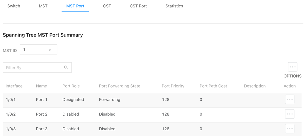
Configurable options include:
-
Port Priority — The priority for the port within the MSTI. This value is used to determine which interface becomes the root port when two ports have the same least-cost path to the root. The port with the lower priority value becomes the root port. If the priority values are the same, the port with the lower interface index becomes the root port.
-
Port Patch Cost — The path cost from the port to the root bridge.
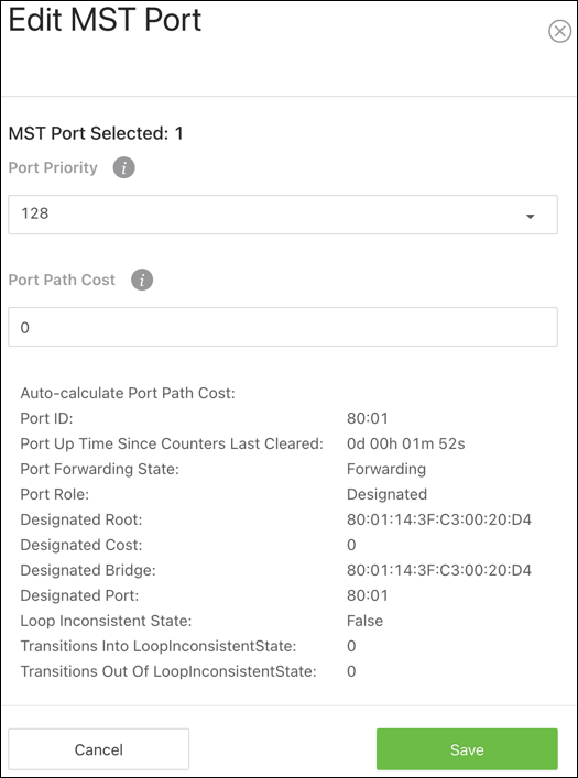
Table field descriptions:
-
Auto-calculate Port Path Cost — Shows whether the path cost from the port to the CIST root is automatically determined by the speed of the interface (Enabled) or configured manually (Disabled).
-
Port ID — A unique value that is automatically generated based on the port priority value and the interface index.
-
Port Up Time Since Counters Last Cleared — The amount of time that the port has been up since the counters were cleared.
-
Port Forwarding State — How traffic is flowing through the port. States include:
-
Blocking — Blocks the flow of traffic. When a device is first connected to a port, it enters the blocking state.
-
Learning — The port is relaying information from a high-priority BPDU to the other ports on the switch.
-
Disabled — Disables the port.
-
Err-disabled — Allows STP to block the flow of traffic when it detects a loop, or forward traffic to a port if the connection changes.
-
-
Port Role — The role of the port within the CST, which is one of the following:
-
Root - A port on the non-root bridge that has the least-cost path to the root bridge.
-
Designated — A port that has the least-cost path to the root bridge on its segment.
-
Alternate — A blocked port that has an alternate path to the root bridge.
-
Backup — A blocked port that has a redundant path to the same network segment as another port on the bridge.
-
Master — The port on a bridge within an MST instance that links the MST instance to other STP regions.
-
Disabled — The port is administratively disabled and is not part of the spanning.
-
-
Designated Root — The bridge ID of the root bridge for the CST.
-
Designated Cost — The path cost offered to the LAN by the designated port.
-
Designated Bridge — The bridge ID of the bridge with the designated port.
-
Designated Port — The port ID of the designated port.
-
Loop Inconsistent State — Identifies whether the interface is currently in a loop-inconsistent state. An interface transitions to a loop-inconsistent state if Loop Guard is enabled and the port stops receiving BPDUs. In this state, the interface does not transmit frames.
-
Transitions Into Loop Inconsistent State — The number of times this interface has transitioned into loop-inconsistent state.
-
Transitions Out Of Loop Inconsistent State — The number of times this interface has transitioned out of loop-inconsistent state.
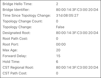
CST
Use the CST Configuration page to configure the Common Spanning Tree (CST) settings. The settings and information on this page define the device within the spanning tree topology that connects all STP/RSTP bridges and MSTP regions.
Configurable settings include:
-
Bridge Priority — This value affects the likelihood that the bridge is selected as the root bridge. A lower value increases the probability that the bridge is selected as the root bridge. For more information, read Understanding Spanning Tree Protocol (STP) & Best Practices for more information.
-
Bridge Max Age — The amount of time a bridge waits before implementing a topological change.
-
Bridge Forward Delay — The amount of time a bridge remains in a listening and learning state before forwarding packets.
-
BPDU Filter — When enabled, this feature filters the BPDU traffic on the switch’s edge ports. When spanning tree is disabled on a port, BPDU filtering allows BPDU packets received on that port to be dropped.
-
BPDU Guard — When enabled, this feature can disable edge ports that receive BPDU packets. This prevents a new device from entering the existing STP topology, so devices that were originally not a part of STP are not allowed to influence the STP topology.
Pro Tip: Do not enable this feature unless there’s a specific use case for it.
-
Spanning Tree TX Hold Count — The maximum number of BPDUs that a bridge is allowed to send within a hello time window.
The bottom of the page provides general CST information.
CST Port
Use the CST Port page to view and configure the Common Spanning Tree (CST) settings for each port on the switch.
Click the Options () button to Refresh the statistics in the table, or to Edit multiple interfaces at once. Click Action to edit an individual interface.
Configurable settings include:
-
Port Priority — The priority for the port within the CST.
-
Admin Edge Port — Enable to force the interface to act as an edge port. An edge port is an interface that is directly connected to a host and is not at risk of causing a loop.
-
Port Path Cost — The path cost from the port to the root bridge.
-
External Port Path Cost — The cost of the path from the port to the CIST root. This value is important if the network includes multiple regions.
-
Port Mode — Select whether STP should be enabled or disabled on the interface.
-
Auto Edge — Enable to allow the interface to become an edge port if it does not receive any BPDUs within a given amount of time.
-
Root Guard — Enable to allow the interface to discard any superior information it receives to protect the root of the device from changing by entering a discarding state, so it does not forward any frames.
-
Loop Guard — Enable to prevent an interface from erroneously transitioning from blocking state to forwarding when the interface stops receiving BPDUs. The interface is marked as being in a loop-inconsistent state, which does not forward frames.
-
TCN Guard — When enabled, TCN Guard restricts the interface from propagating any topology change information received through the interface.
-
BPDU Filter — When enabled, BPDU traffic is filtered on the edge ports. Edge ports do not need to participate in the spanning tree, so BPDU filtering allows BPDU packets received on edge ports to be dropped.
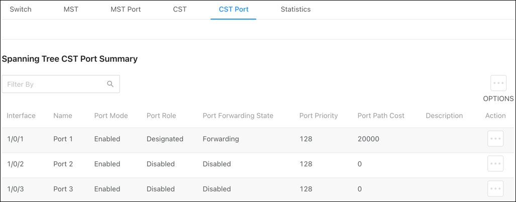
Table field descriptions:
-
Interface — The port number.
-
Name — The name given to the port. Configurable on Settings > Ports > General > Port Summary page.
-
Port Mode — The role of the port within the CST, which is one of the following:
-
Root - A port on the non-root bridge that has the least-cost path to the root bridge.
-
Designated — A port that has the least-cost path to the root bridge on its segment.
-
Alternate — A blocked port that has an alternate path to the root bridge.
-
Backup — A blocked port that has a redundant path to the same network segment as another port on the bridge.
-
Master — The port on a bridge within an MST instance that links the MST instance to other STP regions.
-
Disabled — The port is administratively disabled and is not part of the spanning.
-
-
Port Forwarding State — How traffic is flowing through the port. States include:
-
Blocking — Blocks the flow of traffic. When a device is first connected to a port, it enters the blocking state.
-
Learning — The port is relaying information from a high-priority BPDU to the other ports on the switch.
-
Disabled — Disables the port.
-
Err-disabled — Allows STP to block the flow of traffic when it detects a loop, or forward traffic to a port if the connection changes.
-
-
Port Priority — The port’s location in the network topology and how well it’s situated to pass traffic.
-
Port Path Cost — The path cost from the interface to the CST regional root.
-
Description — Whether the port is permitting or denying traffic.
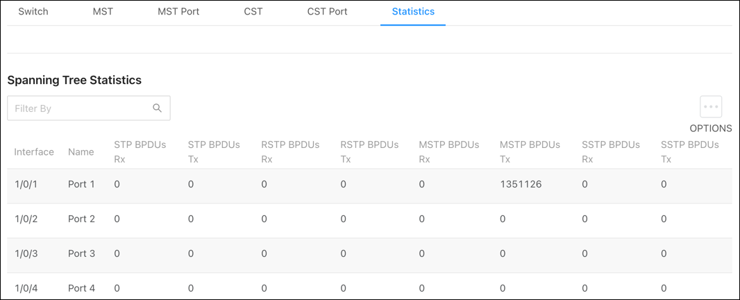
Statistics
Use this page to view how many BPDUS have been transmitted and received on individual ports. Click the Options button, then Refresh to get the latest statistics.
Unregistered Multicast Behavior
Configuration
Use this page to configure how the switch should handle unregistered multicast traffic.
Unregistered Multicast Action options include:
-
Drop — The switch does not forward unregistered multicast packets to the interfaces.
-
Forward — Unregistered multicast packets are forwarded to all active interfaces on the switch but not to the CPU, to reduce overhead.
-
Forward Including CPU — Unregistered multicast packets are forwarded to all active interfaces on the switch and the CPU.
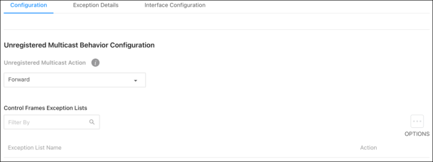
Exception Lists display the default ACL exception list available on the switch.
Exception Details
Use this page to configure which Multicast addresses and destination ports should be allowed to continue flooding while the Unregistered Multicast Behavior is set to Drop.
Use the Exception List Name dropdown to select the list you’d like to edit on the page.
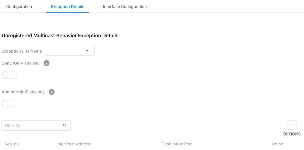
Configurable settings include:
-
Deny IGMP any any — Deny every IGMP packet.
-
Add permit IP any any — Add a permit any any rule at the latest sequence.
Click the Options () button to Edit the lists configured in the switch or Refresh the page.
Options include:
-
Seq. no — The ACL rule number for each exception entry.
-
Multicast Address — The multicast address allowed to flood.
-
Destination Port — The optional destination port for traffic destinated for the multicast address. This can be left blank to specify any port, a single port, or a range of ports using “-“.
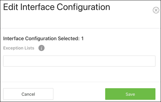
Interface Configuration
Use this page to configure which Exception Lists are applied to each port.
Click the Options () button to Edit multiple ports are once or to Refresh the page. Click the Action button to edit a single port at a time.
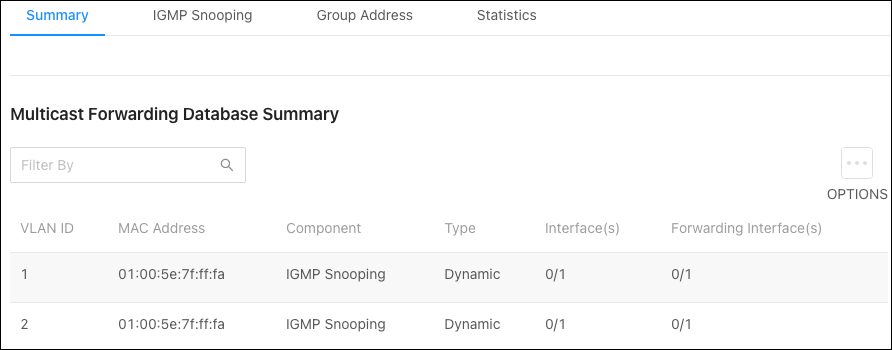
Multicast Forwarding Database
Summary
Use this page for a summary of the multicast data collected by the switch. Click Options, then Refresh to get the latest information.
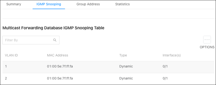
IGMP Snooping
Use this table to gather information about the IGMP snooping traffic collected by the switch.
Click Options (), then Refresh to get the latest information or click Clear to reset the table.
Note: Not all multicast traffic is handled by IGMP snooping. Read Understanding Spanning Tree Protocol (STP) & Best Practices for more information.
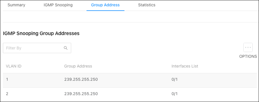
Group Address
Use this table to see the multicast group addresses the switch has recorded. Click Options (), then Refresh to get the latest information.
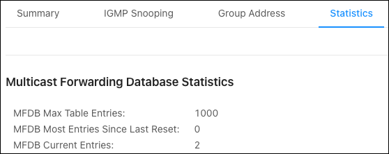
Statistics
Use this page to view multicast statistics the switch has gathered.
Loop Protection
Loop Protection detects loops in downstream switches that do not have spanning tree configured. When a loop-protected interface detects a loop, it can disable itself.
Caution: Do not use Loop Protection on uplink ports between switches with spanning tree enabled. Loop Protection is designed for unmanaged switches that drop spanning tree BPDUs.
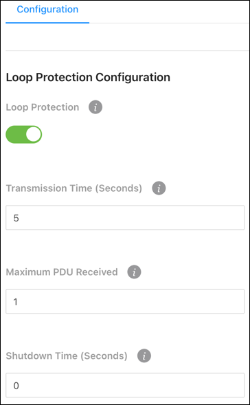
Loop Protection Configuration
Loop Protection sends loop protection protocol data units (PDUs) to the multicast address 01:80:C2:00:00:08. When an interface receives a PDU, it compares the source MAC address with the switch’s. If the MAC address matches a loop is detected and a configured action is taken. Shutdown Port, Shutdown Port and Log, or Log Only.
To configure Loop Protection:
-
Enable Loop Protection globally for the switch.
-
Enter a Transmission Time (in seconds) that the switch sends PDU packets on Loop Protected interfaces. The default is 5.
-
Enter an amount for the Maximum PDU Received that the interface can receive before taking the configured action. The default is 1.
-
Enter the Shutdown Time (in seconds) that the interface shuts down when a loop is detected. The default is 0.
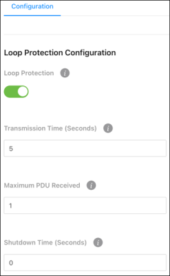
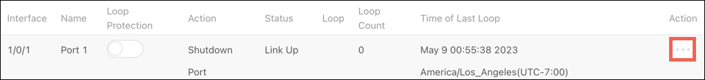
-
Click the Action (
)button for the interface you’d like to configure or use the Options button > Edit to select multiple interfaces to configure at once.
Note: You can quickly enable Loop Protection using the toggle in each row.
-
A new window appears with configurable options. Enable Loop Protection on the interface, then select an Action to take. Shutdown Port, Shutdown Port and Log, or Log Only. Then, click Save.
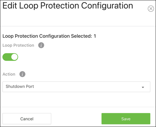
-
The window closes and you return to the Loop Protection Configuration table. Click Apply at the top of the page.
The Loop Protection Configuration table gives an overview of what interfaces have Loop Protection enabled, how they’re configured, and the Time of Last Loop.
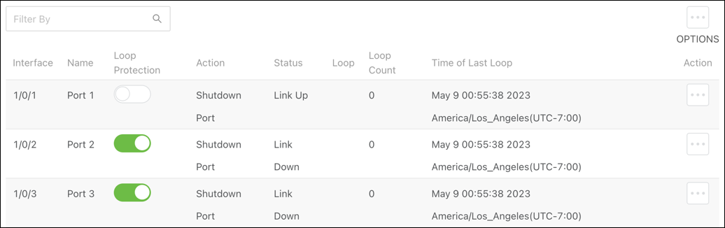
Table field descriptions:
-
Interface — The switchport or LAG number.
-
Name — The name configured for the switchport or LAG.
-
Loop Protection — Displays if Loop Protection is enabled or disabled on the port. Click to toggle this setting.
-
Action — The action taken when a loop is detected on the interface.
-
Status — Displays if the interface link is up or down.
-
Loop — Indicates if there is a loop currently detected. The field is blank when there is no loop detected.
-
Loop Count — The number of loops that have been detected on the interface.
-
Time of Last Loop — The date and time of the last loop detected on the interface.
Private VLAN
Private VLANs provide port-based security and isolation between ports within the assigned VLAN. Traffic on ports assigned to a private VLAN can only be forwarded to and from uplink ports.
Configuration
Click the Options () button to Edit multiple VLAN IDs at once or to Refresh the page. Click the Action button to configure a single VLAN.
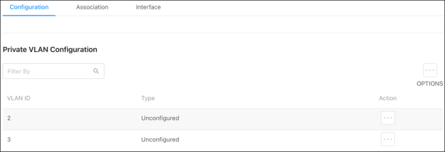
A VLAN can be one of the following Types:
-
Unconfigured — The VLAN is not configured as a private VLAN.
-
Primary — A private VLAN that forwards the traffic from the promiscuous ports to isolated ports, community ports, and other promiscuous ports in the same private VLAN. Only one primary VLAN can be configured per private VLAN. All ports within a private VLAN share the same primary VLAN.
-
Isolated — A secondary VLAN that carries traffic from isolated ports to promiscuous ports. Only one isolated VLAN can be configured per private VLAN.
-
Community — A secondary VLAN that forwards traffic between ports that belong to the same community and to the promiscuous ports. Multiple community VLANs can be configured per private VLAN.
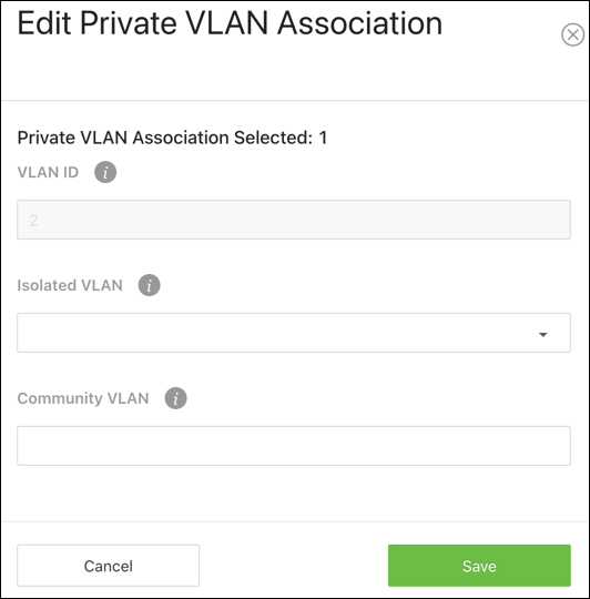
Association
Use the Association page to assign an Isolated or Community VLAN to a Primary VLAN.
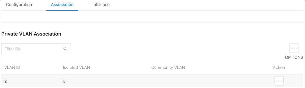
Click the Options () button to Edit multiple VLAN IDs at once or to Refresh the page. Click the Action button to configure a single VLAN.
Interface
Use this page to configure the private VLAN mode for each interface.
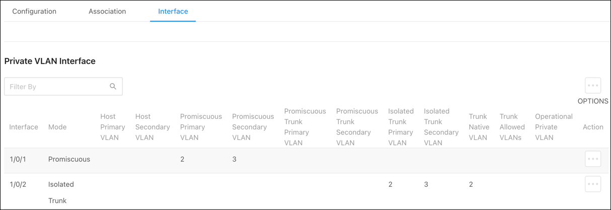
Click the Options () button to Edit multiple VLAN IDs at once or to Refresh the page. Click the Action button to configure a single VLAN.
The interface(s) can be set to one of the following modes:
-
General — The interface is not a member of a private VLAN.
-
Promiscuous — The interface belongs to a primary VLAN and can communicate with all interfaces in the private VLAN, including other promiscuous ports, community ports, and isolated ports.
-
Isolated Trunk — The interface also belongs to a primary VLAN. It carries traffic from isolated ports to promiscuous ports. Only one isolated VLAN can be configured per private VLAN. An isolated trunk port carries tagged traffic of multiple isolated VLANs and normal VLANs.
-
Promiscuous Trunk — The interface belongs to a primary VLAN and can communicate with all interfaces in the private VLAN, including other promiscuous trunk ports, community ports, and isolated ports.
-
Host — The interface belongs to a secondary VLAN and, depending upon the type of secondary VLAN, can either communicate with other ports in the same community (if the secondary VLAN is a community VLAN) and with the promiscuous ports or is able to communicate only with the promiscuous ports (if the secondary VLAN is an isolated VLAN).
Neighbors
LLDP
Global
Use this page to configure global Link Layer Discovery Protocol (LLDP) settings for the switch. LLDP is a generic protocol used to advertise the device’s capabilities to other devices on the network.
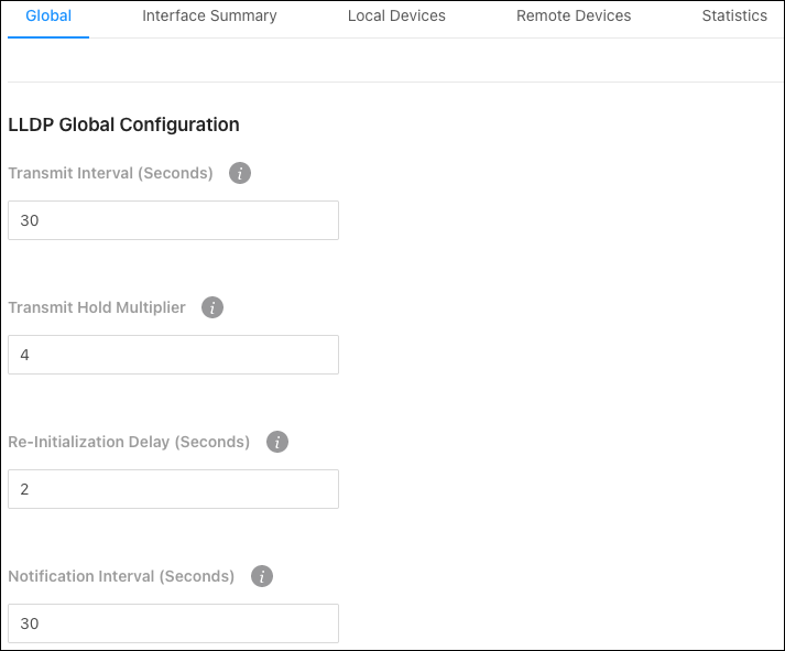
Configurable settings include:
-
Transmit Interval (Seconds) — The number of seconds between LLDP transmissions.
-
Transmit Hold Multiplier — Multiply the value entered with the Transmit interval to determine the Time to Live (TTL) value that the switch advertises.
The TTL value is the number of network hops that a packet can take before it’s discarded by the router.
-
Re-Initialization Delay (Seconds) — The number of seconds to wait before attempting to reinitialize LLDP on a port after the port’s LLDP operating mode changes.
-
Notification Interval (Seconds) — The minimum number of seconds to wait between transmissions of SNMP trap notifications on the switch.
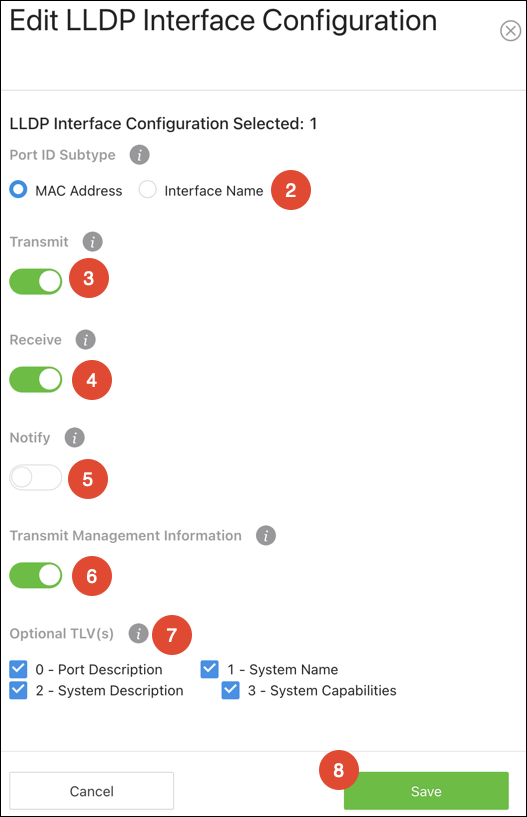
Interface Summary
Use this page to configure LLDP settings on individual ports.
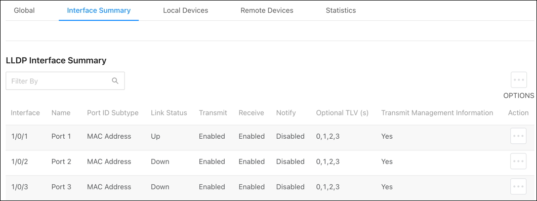
To configure LLDP on a port(s):
-
Click the Options button to edit multiple ports, or the Action button to edit an individual port.
-
For Port ID Subtype, select if you’d like LLDP to advertise the port’s MAC address or the Interface Name.
-
Enable or disable if the port can Transmit or Receive LLDP advertisements.
-
Toggle Receive on so the device can receive LLDPDUs from other devices.
-
Toggle Notify on for the interface to send SNMP notifications when a link partner device is added or removed.
-
Enable Transmit Management Information so other remote management devices on the network can locate the switch.
-
Select Optional TLV(s) for the switch to advertise.
-
Click Save, then Apply at the top of the page.
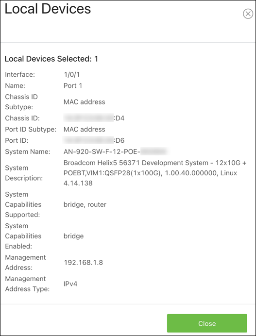
Local Devices
Use this page to gather LLDP information about the switchports.
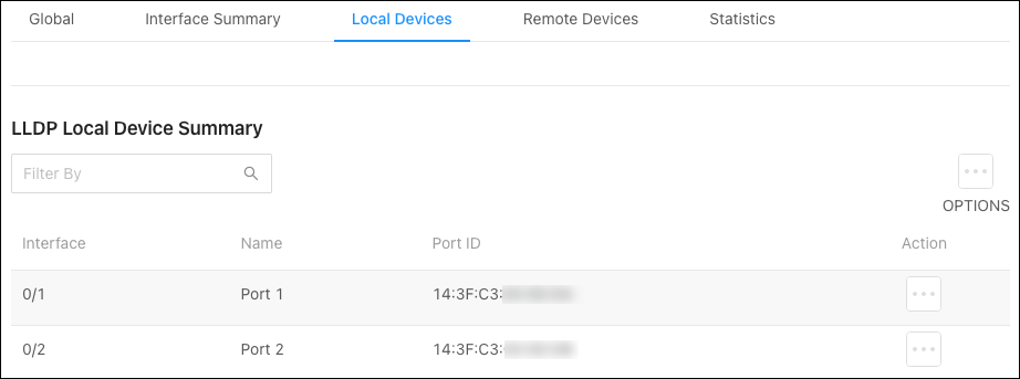
Click the Actions () button to get more information about the port.
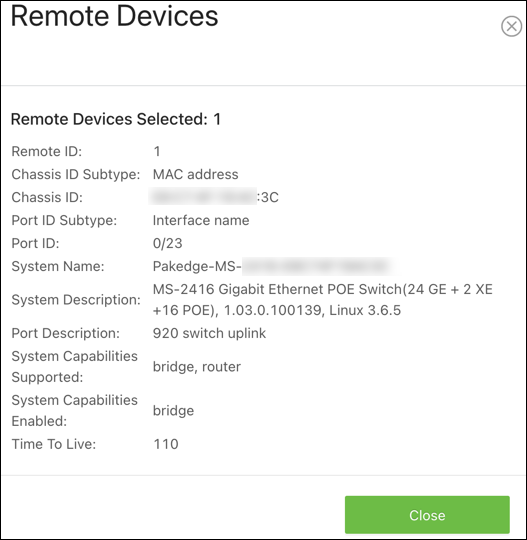
Remote Devices
Use this page to view LLDP information collected by the device connected to the switch’s port.
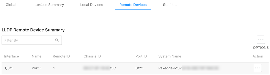
Click the Actions button to get more information about the connected device.
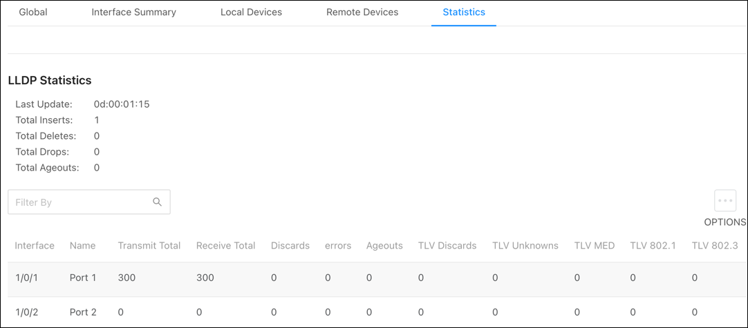
Statistics
Use this page to view LLDP counts. Click Options(), then Refresh to get the most up-to-date information. Click Clear to reset the table.
LLDP-MED
Global
LLDP-MED is an extension of LLDP. MED stands for Media Endpoint Device and is typically used for voice over IP (VoIP).
Note: LLDP and LLDP-MED cannot operate simultaneously. If a device receives LLDP packets it cannot send LLDP-MED packets until it receives LLDP-MED packets. Likewise, for LLDP.
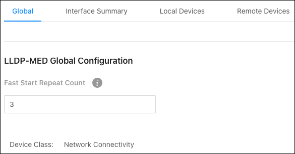
Use this page to enter a value for the Fast Start Repeat Count. This is the number of LLDP-MED Protocol Data Units (PDUs) that can be transmitted.
Click Apply to save changes.
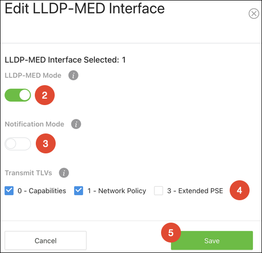
Interface Summary
Use this page to configure LLDP-MED settings on individual ports.
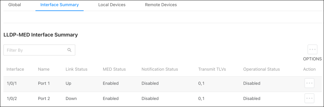
To configure LLDP-MED on a port(s):
-
Click the Options (
) button to edit multiple ports, or the Action button to edit an individual port. -
Enable or disable LLDP-MED on the port.
-
Enable or disable Notification Mode to be notified of topology changes.
-
Select optional Transmit TLVs to advertise.
-
Click Save, then Apply at the top of the page.

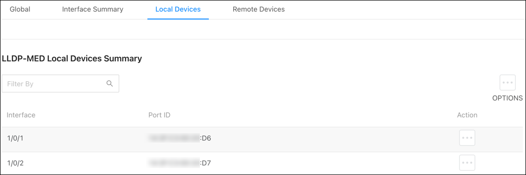
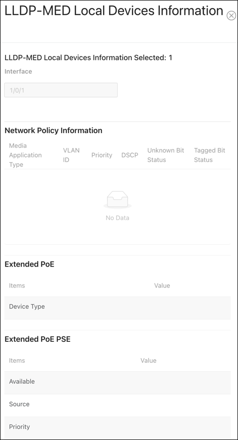
Local Devices
Use this page to gather LLDP-MED information about the switchports.
Click the Actions () button to get more information about the port.
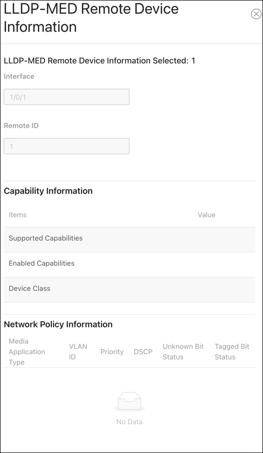
Remote Devices
Use this page to view LLDP-MED information collected by the device connected to the switch’s port.
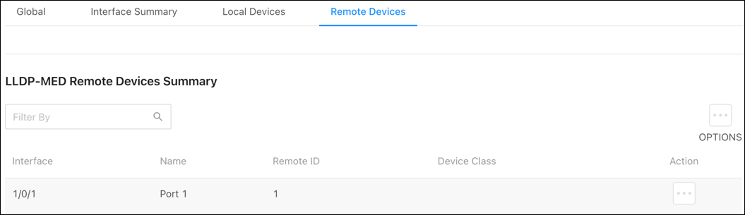
Click the Actions () button to get more information about the port.
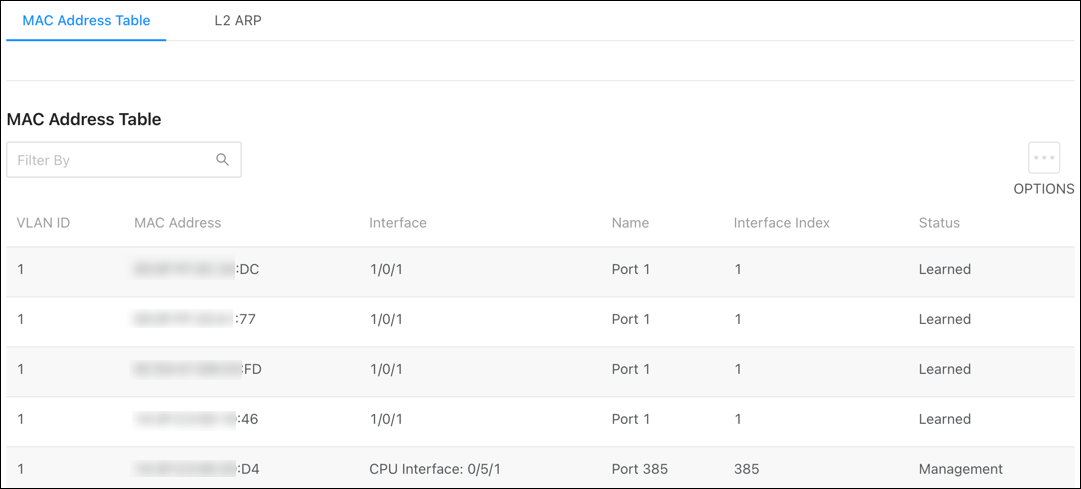
MAC Address Table
Use the page to see which MAC addresses the switch has recorded traffic from on a port(s) and which VLAN they’re a member of. Use the Options button to refresh the page, or to select how many rows to display.
Pro Tip: Use the Filter By field to search for MAC addresses.
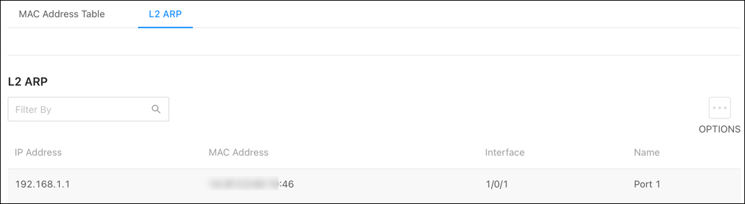
L2 ARP
This pages displays the learned IP and MAC address of connected devices on each interface.
ARP Table
Summary
The ARP table displays MAC and IP address of devices that have communicated with the switch.
Use the Options() button to refresh the page or clear the table. Use the Action button to delete an individual entry.
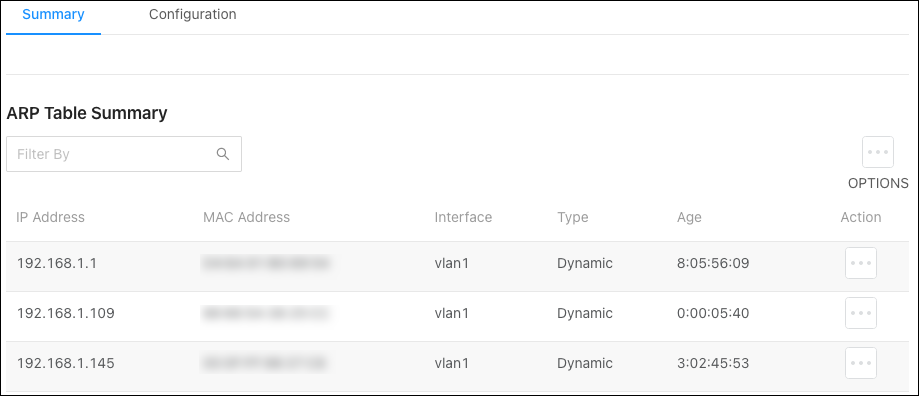
Table fields include:
-
IP Address — The IP address of the device.
-
MAC Address — The MAC address of the device.
-
Interface - The VLAN ID associated with the device.
-
Type – The type of IP address the device is broadcasting. Dynamic or static.
Note: Devices with MAC reservations appear as dynamic.
-
Age – How long the switch has seen the connection to the device. (Days:Hours:Minutes:Seconds)
Configuration
Use this page to configure the ARP Table’s settings.
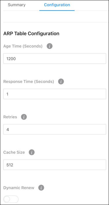
Configurable settings include:
-
Age Time (Seconds) — The amount of time that a dynamic ARP entry remains in the ARP table before aging out.
-
Response Time (Seconds) — The amount of time, that the device waits for an ARP response to an ARP request that it sends.
-
Retries — The number of attempts the switch will send an ARP request if an ARP response isn’t received. This number includes the initial ARP request.
-
Cache Size — The maximum number of entries allowed in the ARP table. This number includes all static and dynamic ARP entries.
-
Dynamic Renew — Enable to allow the switch to automatically renew dynamic ARP entries when they age out.
Routing
Araknis 920 switches support layer 3 routing to create routes between interfaces and PIM-SM (sparse mode) for multicast traffic.
IP IGMP Interface
Configuration
Use this page to enable IGMP routing.
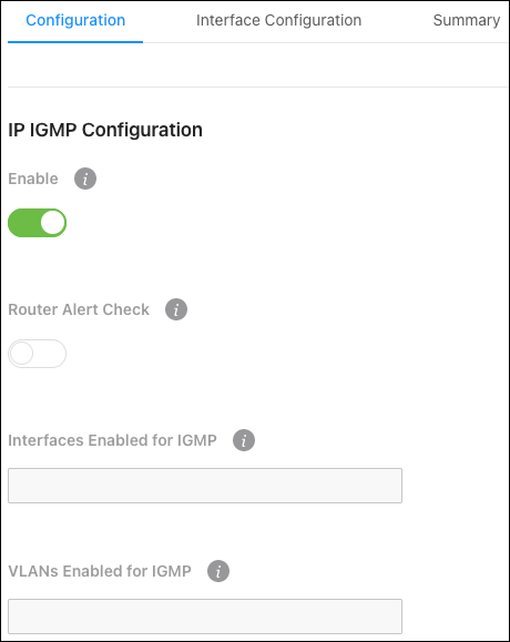
Configurable options include:
-
Enable — Enables IGMP on the device.
-
Router Alert Check — Enable for the switch to inspect packets when they are being forwarded, even though the packet is not directly addressed to this switch.
-
Interfaces Enabled for IGMP — Displays the interfaces with IGMP administratively enabled.
-
VLANs Enabled for IGMP — Displays the VLANs with IGMP administratively enabled.
Interface Configuration
Use this page to configure IGMP on a per-interface level.
Click the Options () button to edit multiple interfaces at once, or the Action button to edit a single interface. There’s also a toggle to quickly enable or disable the IGMP settings on the interface.
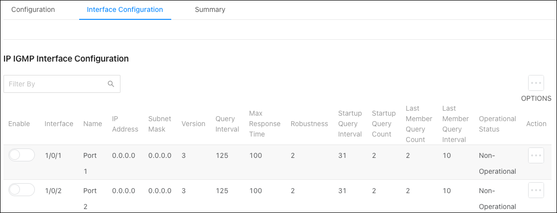
Configurable options include:
-
Enable — Enables the administrative IGMP settings on the interface.
-
Version — Select the IGMP version being used.
-
Query Interval — Enter the amount of time the IGMP snooping querier on the device should wait between sending periodic IGMP queries.
-
Max Response Time — Enter the number of seconds the interface should wait after sending a query if it does not receive a report for a particular group. The value should be less than the Group Membership Interval.
-
Robustness — Enter the number of times an IGMP query should be sent in case of packet loss. A higher value increases the timeout time for multicast groups.
-
Startup Query Interval — Enter an interval for the IGMP querier to send general inquiries at startup.
-
Startup Query Count — Enter the number of queries to send at startup.
-
Last Member Query Count — For IGMPv2, this is the number of group-specific queries a querier sends after receiving a leave message. For IGMPv3, this is the number of group-and-source-specific queries that a querier sends after receiving a report that changes multicast source and group mappings.
-
Last Member Query Interval — For IGMPv2, this is the interval a querier sends group-specific queries after receiving a leave message. For IGMPv3, this is the interval a querier sends group-and-source-specific queries after receiving a report that changes multicast source and group mappings.
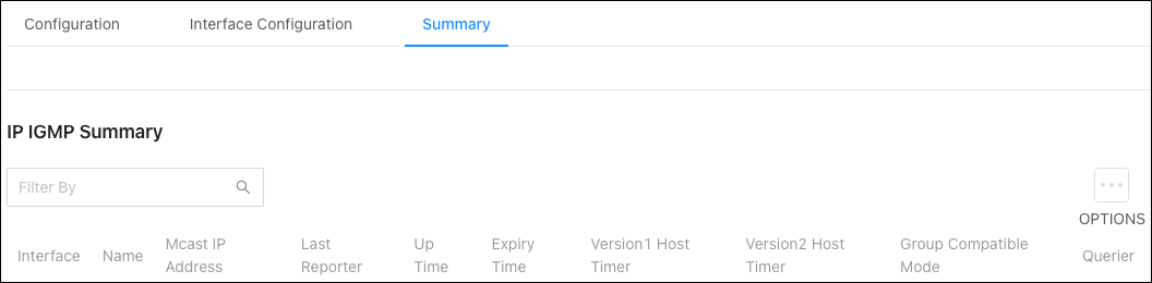
Summary
This page displays a summary of the IGMP settings configured on each interface. Use the Options () button to refresh the table.
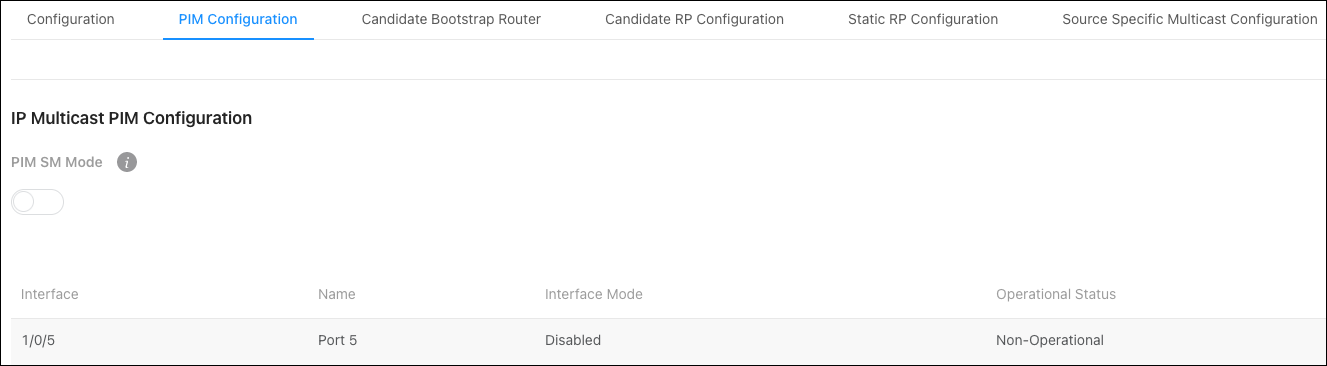
PIM Configuration
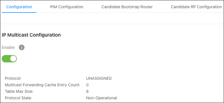
Use this page to administratively enable Protocol Independent Multicast (PIM) globally.
Candidate Bootstrap Router
Use this page to configure the Bootstrap Router (BSR).
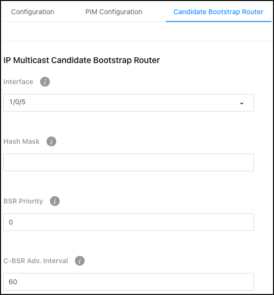
Configurable settings include:
-
Interface — Select the interface to configure.
-
Hash Mask — Specify the hash mask length to use in BSR messages.
-
BSR Priority — Specify the BSR priority to use in BSR messages.
-
C-BSR Adv. Interval — Enter the BSR message transmission interval in seconds.
Candidate RP Configuration
Use this page to configure a Candidate RP (Rendezvous Point). Select an Interface from the dropdown, then click Options (), thenAdd to configure an RP.
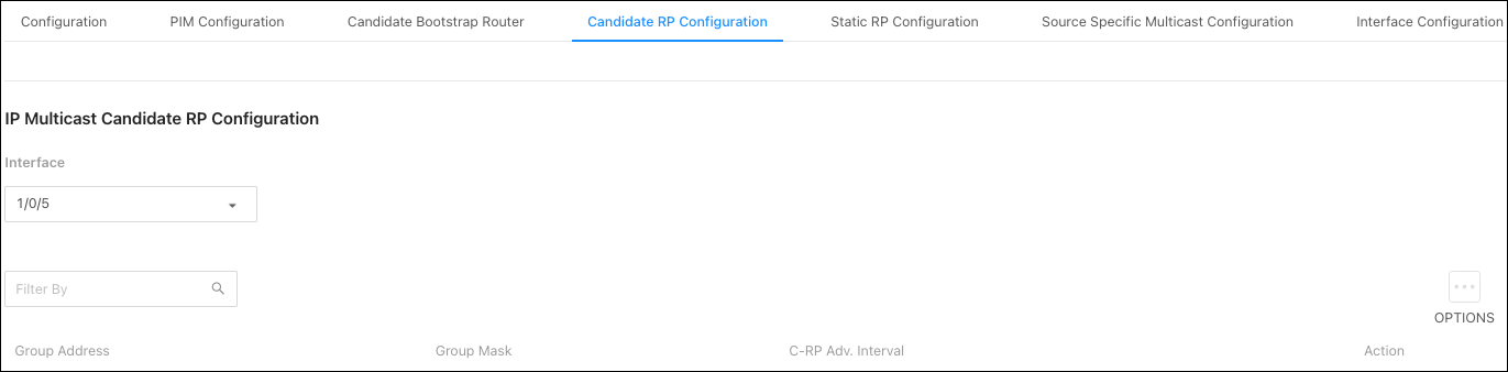
Settings include:
-
Group Address — Enter the IP address of router interface.
-
Group Mask — Enter the subnet mask fo the router interface.
-
C-RP Adv. Interval — Enter the BSR message transmission interval in seconds.
Static RP Configuration
Use this page to configure a Static RP (Rendezvous Point). Click Options (), then Add to configure an RP.
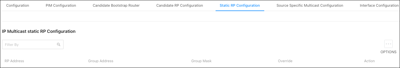
Settings include:
-
RR Address — Enter the IP address of the router acting as the RP for a group range.
-
Group Address — Enter the IP address of the router interface.
-
Group Mask — Enter the subnet mask of the router interface.
-
Override — Enable to allow the static RP to take precedence over auto-RP for the group range.
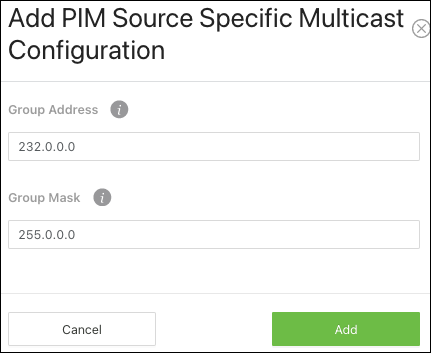
Source Specific Multicast Configuration
Use this page to configure a PIM Source Specific Multicast Group. Click Options (), then Add to configure a group.
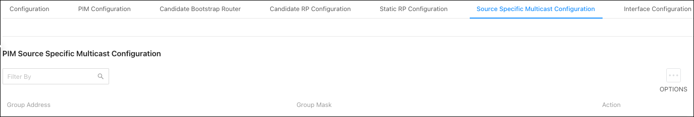
The new window asks for a Group Address and Group Mask.
Interface Configuration
Use this page to configure multicast on a per-interface level.
Click the Options () button to edit multiple interfaces at once, or the Action button to edit a single interface. There’s also a toggle to quickly enable or disable the IGMP settings on the interface.
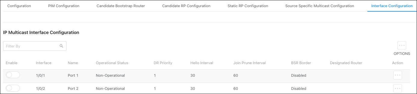
Configurable options include:
-
Enable — Enables the PIM on the interface.
-
BSR Border — Enable to prevent BSR messages from being sent or received through the interface.
-
DR Priority — Enter a Designated Router (DR) priority for the interface. The interface with the highest priority is elected DR.
-
Hello Interval — Enter the frequency that PIM hello messages are sent on the interface in seconds.
-
Join Prune Interval — Enter a Join/Prune Interval for the specified interface.
IP Mutlicast Information
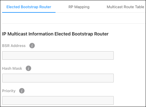
Elected Bootstrap Router
This page displays information about the elected Bootstrap Router (BSR).
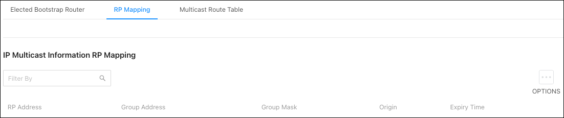
RP Mapping
This page displays information about the RP (Rendezvous Points) on the switch. Use the Options () button to refresh the page.
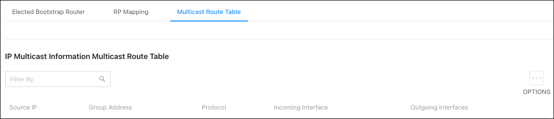
Multicast Route Table
This page displays information about the multicast routes on the switch. Use the Options () button to refresh the page.
Router
Configuration
Use this page to enable or disable the routing feature of the switch.
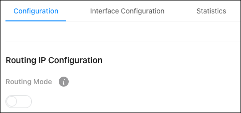
Configurable settings include:
-
Routing Mode — Enable for the switch to act as a Layer 3 device by routing packets between interfaces configured for IP routing.
-
ICMP Echo Replies — Enable to allow the device to send ICMP Echo Reply messages in response to ICMP Echo Request (ping) messages it receives.
-
ICMP Redirects — Enable to allow the device to send ICMP Redirect messages to hosts. An ICMP Redirect message notifies a host when a better route to a particular destination is available on the network segment.
-
ICMP Rate Limit Interval — Enter the maximum burst interval for ICMP error messages transmitted by the switch. The rate limit for ICMP error messages is configured as a token bucket. The ICMP Rate Limit Interval specifies how often the token bucket is initialized with tokens of the size configured in the ICMP Rate Limit Burst Size field.
-
ICMP Rate Limit Burst Size — Enter the number of ICMP error messages that can be sent during the burst interval configured in the ICMP Rate Limit Interval field.
-
Static Route Preference — The default distance (preference) for static routes. Lower route-distance values are preferred when determining the best route. This value is used when using the CLI to configure a static route and no preference is specified. Changing the Static Route Preference does not update the preference of existing static routes.
-
Global Default Gateway — The gateway IP address that the switch uses. If the destination IP address in a packet does not match any routes in the routing table, the packet is sent to the default gateway. The gateway specified in this field is preferable to a default gateway learned from a DHCP server.
Interface Configuration
Use this page to enable and configure routing on specific interfaces. Each interface is disabled by default.
Use the Options () button to add a VLAN, or the Action button in an interface row to configure routing features.
Each row has a toggle to quickly enable or disable the interface.
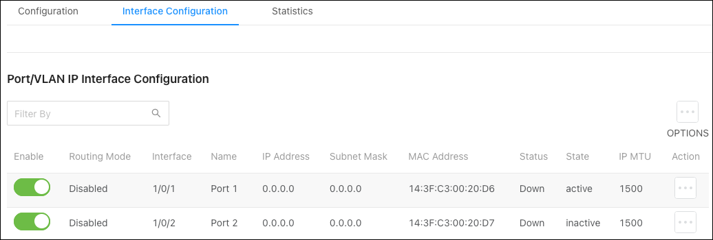
Configurable options include:
-
Type — The type of interface being configured.
-
Interface — The type of interface being configured. VLAN or Interface (port).
-
Routing Mode — Enable to use the routing feature on the interface.
-
Enable — Enables the port to forward traffic.
-
IP Address Configuration Method — Select the method that the interfaces obtain an IP Address. Options include:
-
None — The interface does not receive an IP address.
-
Manual — Select this option to use the fields below to configure the interface’s IP address and subnet mask.
-
DHCP —The interface automatically obtains an IP address from the DHCP server.
-
-
DHCP Client Identifier — Also known as Option 61, is used by DHCP clients to specify their unique identifier. DHCP servers use this value to index their database of address bindings. This value is expected to be unique for all clients in an administrative domain. The Client Identifier string is displayed beside the check box when DHCP is enabled on the port with the Client Identifier option enabled. This web page must be refreshed once this change is made.
-
IP Address — Only available when the interface IP Address Configuration Method is set to Manual.
-
Subnet Mask — Only available when the interface IP Address Configuration Method is set to Manual.
-
IP MTU — Enter the largest IP packet size the interface can transmit, in bytes. The Maximum Transmission Unit (MTU) is the maximum frame size minus the length of the Layer 2 header.
-
Bandwidth — Configure the bandwidth on the interface. This setting communicates the speed of the interface to higher-level protocols.
-
Encapsulation Type — The link layer encapsulation type for packets transmitted from the interface. Ethernet is the only option.
-
Forward Net Directed Broadcasts — Enable to forward network-directed broadcasts. If this option is clear, network-directed broadcasts are dropped. A network-directed broadcast is a broadcast directed to a specific subnet.
-
Destination Unreachables — When enabled, the interface is allowed to send ICMP Destination Unreachable message to a host if the intended destination cannot be reached. If this option is clear, the interface does not send ICMP Destination Unreachable messages.
-
ICMP Redirects — When enabled, the interface is allowed to send ICMP Redirect messages to notify a host when a better route to a particular destination is available on the network segment. ICMP Redirects must be enabled both globally, and on the interface, to work.
-
Proxy ARP — Enable for the interface to be able to respond to an ARP request for a host other than itself. An interface can act as an ARP proxy if it is aware of the destination and can route packets to the intended host, which is on a different subnet than the host that sent the ARP request.
-
Local Proxy ARP — When enabled, the interface can respond to an ARP request for a host other than itself. Unlike proxy ARP, local proxy ARP allows the interface to respond to ARP requests for a host that is on the same subnet as the host that sent the ARP request. This is useful when a host is not permitted to reply to an ARP request from another host in the same subnet, like when using the protected ports feature.
Statistics
This page displays IP traffic counters.
IP Routing
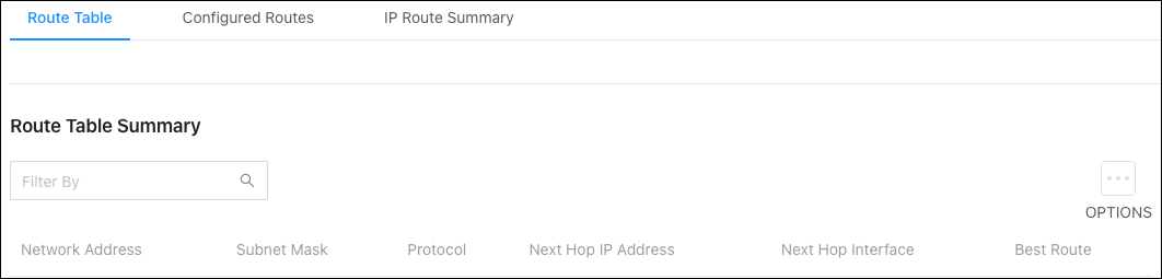
Route Table
This table displays information about routes on the switch. Use the Options () button to refresh the table.
Configured Routes
Use this page to view and configure routes on the switch. Click the Options () button to add a new route.
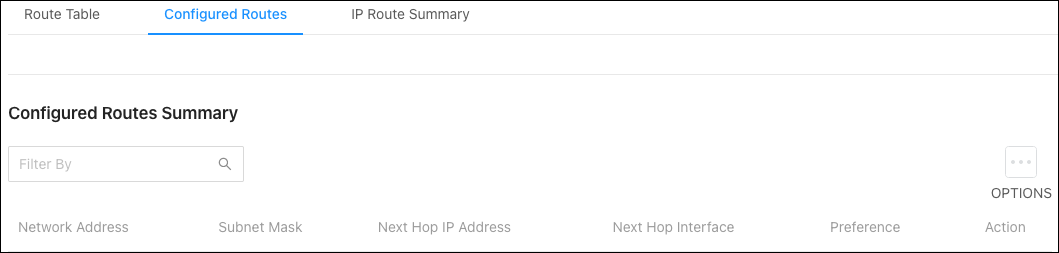
Configurable settings include:
-
Route Type — Select one of the following routes to configure:
-
Default — The route the device uses to send a packet if the routing table does not contain a longer matching prefix for the packet's destination. The routing table can contain only one default route.
-
Static — A manually added route.
-
Static Reject — A route where packets that match the route are discarded instead of forwarded. The device might send an ICMP Destination Unreachable message.
-
-
Network Address — Enter the IP route prefix for the destination network. This IP address must contain only the network portion of the address and not the host bits. When adding a default route, this field must be 0.0.0.0.
-
Subnet Mask — Enter the IP subnet mask (also known as the network mask or netmask) associated with the network address. The subnet mask defines which portion of an IP address belongs to the network prefix, and which portion belongs to the host identifier. When adding a default route, this field must be 0.0.0.0.
-
Next Hop IP Address — Enter the outgoing router IP address to use when forwarding traffic to the next router (if any) in the path toward the destination. The next router is always an adjacent neighbor or the IP address of the local interface for a directly attached network. When adding a static reject route, this field must be 0.0.0.0 because the packets are dropped rather than forwarded.
-
Preference — Enter a preference value for the route. A lower preference value is a more preferred route. When the routing table has more than one route to the same network, the device selects the route with the lowest route preference.
IP Route Summary
This page displays a summary of the IP routes and route table counters the switch has collected.
QoS
Class of Service
Class of Service (CoS) allows you to directly configure certain aspects of switch queueing, which allows you to configure Quality of Service (QoS) behavior when the complexities of DiffServ aren’t required. The priority of a packet arriving at an interface can be steered to the appropriate outbound CoS queue through a mapping table. The CoS queue characteristics, such as minimum guaranteed bandwidth and transmission rate shaping, are configurable at the queue or port level.
IP DSCP
Use the IP DSCP Mapping Table to map an IP DSCP value to a Traffic Class.
Click the Action () button to assign individual IP DSCP values to a Traffic Class, or the Options button to assign multiple IP DSCP values to the same Traffic Class.
Click Apply, at the top of the page, when done.
Interface
Use the table to apply an interface shaping rate to individual interfaces or to all at once.
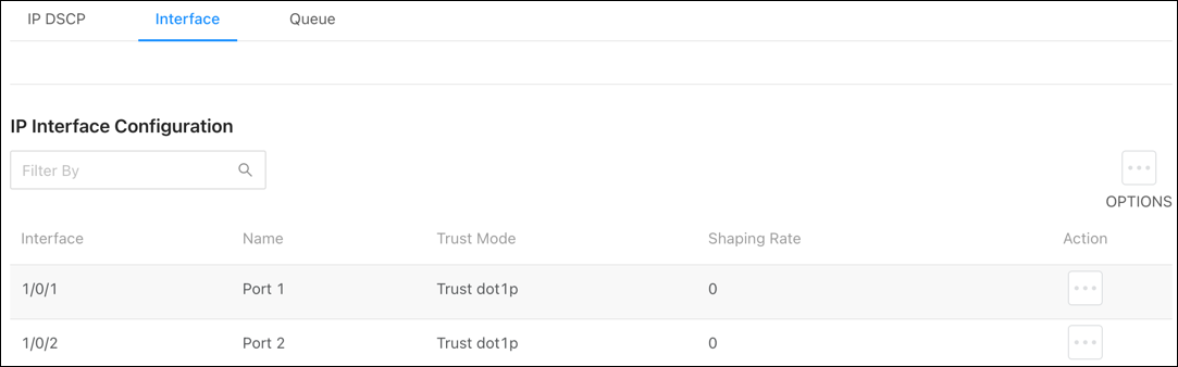
Click the Action () button to edit individual interfaces, or the Options button to edit multiple interfaces at once.
Configurable settings include:
-
Trust Mode — Select the Trust Mode for ingress traffic on the interface. The options are:
-
Untrusted — The interface ignores all priority designations in incoming packets and sends them to a traffic queue based on the ingress port’s default priority.
-
Trust dot1p — The port accepts the designated 8021.p priority encoded in the arriving packets.
-
Trust IP – DSCP: The port accepts the designated IP DSCP priority encoded in the arriving packets.
-
-
Shaping Rate — The maximum amount of traffic that can leave an interface. The specified value is a percentage of the maximum negotiated bandwidth.
Queue
Use this page to designate what a queue does by configuring switch egress queues. Configurable queue parameters include bandwidth allocations and the scheduling of packet transmissions from the set of all queues on a port.
The Total Minimum Bandwidth Allocation is displayed as a percentage at the top of the page.
Use the Restore Default toggle or click Options (), then Refresh to clear all configurations.
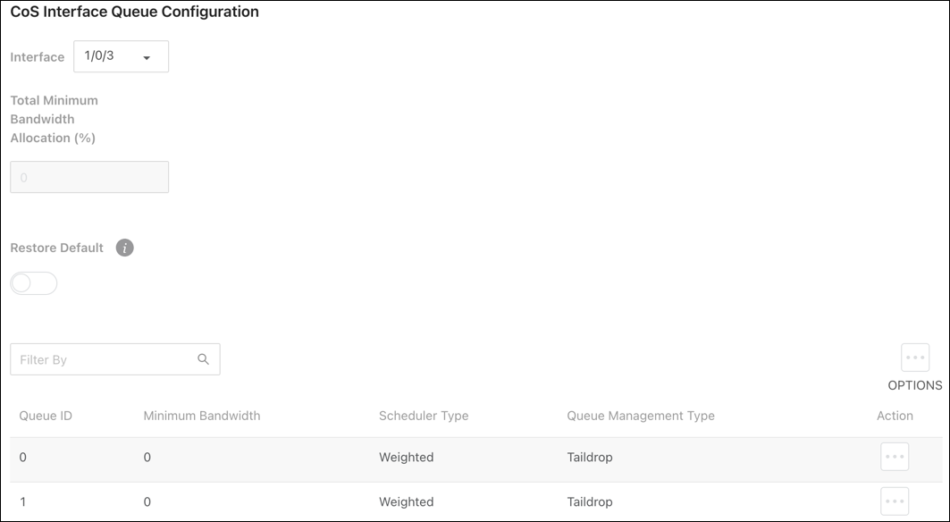
To configure CoS interface queues:
-
Select an Interface. This can be an individual switchport or LAG.
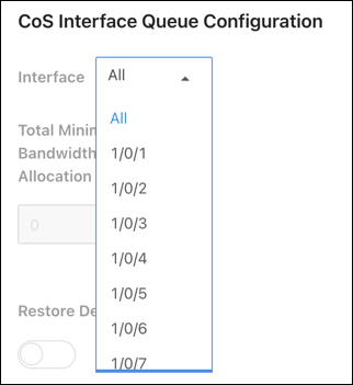
-
Select an individual Queue ID by clicking the Action (
) button in the corresponding row or click the Options button to select multiple Queue IDs to configure. -
Enter a Minimum Bandwidth to allocate to the queue. Setting this value higher than the maximum bandwidth automatically increases the maximum to the same value. A value of zero means there is no guaranteed minimum.
Note: The sum of individual Minimum Bandwidth values for all queues in the selected interface cannot exceed 100.
-
Select one of the following options for Scheduler Type:
-
Weighted — Weighted round robin associates a weight to each queue.
-
Strict — Services traffic with the queue’s highest priority first.
-
Select one of the following Queue Management Types:
-
Taildrop — All packets on a queue are safe until congestion occurs. At this point, any additional packets queued are dropped.
-
WRED — Weighted Random Early Detection (WRED) drops packets selectively based their drop precedence level.
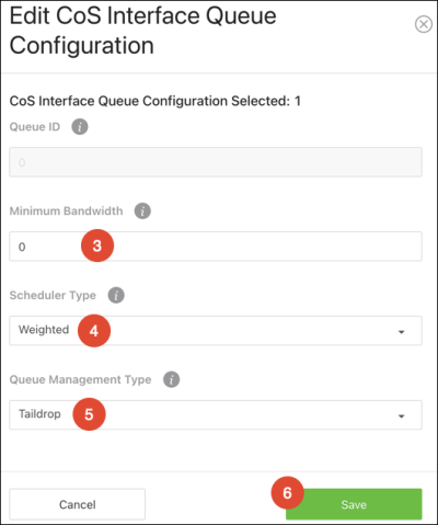
-

-
Click Save and when the window closes, click the Apply button to save changes.
ACL Rules
Access Control Lists (ACLS) make sure that only authorized users have access to specific resources and block unwanted attempts by filtering packets based on rules. ACLs are used to control traffic flow, restrict the contents of routing updates, decide which types of traffic to block or forward, and provide network security. Pakedge MS switches support IPv4 and MAC ACLs.
To create an ACL, you must:
-
Create an ACL rule with an identifier (ACL ID) on the Summary page.
-
Define the ACL rule.
-
Assign the ACL ID to a switch port or VLAN interface.
Summary
Use this page to configure Access Command List (ACL) Rules and enable ACL Counters.
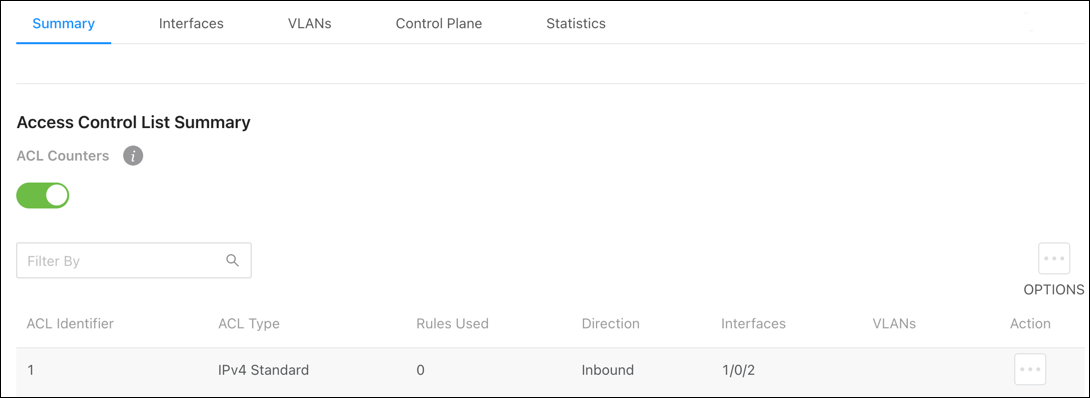
To add an ACL rule:
-
Click Options (
), then Add. -
Select an ACL Type:
-
IPv4 Standard — Match criteria is based on the source address of IPv4 packets.
-
IPv4 Extended — Match criteria can be based on the source and destination addresses, source and destination Layer 4 ports, and protocol type of IPv4 packets. The ACL identifier can be an alphanumeric name instead of a number, known as IPv4 Named in other switches.
-
IPv6 Named — Match criteria can be based on information including the source and destination IPv6 addresses, source and destination Layer 4 ports, and protocol type within IPv6 packets.
-
Extended MAC — Match criteria can be based on the source and destination MAC addresses, 802.1p user priority, VLAN ID, and EtherType value within Ethernet frames.
-
Enter a number for the ACL Identifier.
-
Click Add, then Apply at the top of the page.
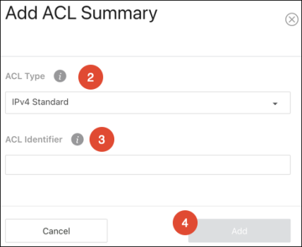

Interfaces
Use this page to add an ACL rule to an interface (port).
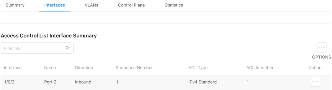
To add an ACL rule to a port:
-
Click Options (
), then Add. -
Select the Interface (port) to apply the ACL rule to.
-
Select a Direction for the packets to be checked against. If the packets should be checked against the ACL rules when the port(s) receives it, select Inbound. Select Outbound if the packets should be checked when the packets are exiting the port(s).
-
Enter a Sequence Number between 1 to 4294967295. Typing 0 auto-generates a sequence number. The order the ACL is applied to traffic on the interface relative to other ACLs associated with the interface in the same direction. When multiple ACLs are applied to the same interface in the same direction, the ACL with the lowest sequence number is applied first, and the other ACLs are applied in ascending numerical order.
-
Select the ACL Identifier of the ACL rule to apply to the port(s).
-
Click Add, then Apply at the top of the page.
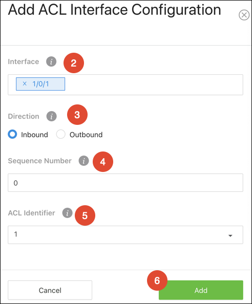
VLANs
Use this page to associate one or more ACLs with one or more VLANs configured on the switch.
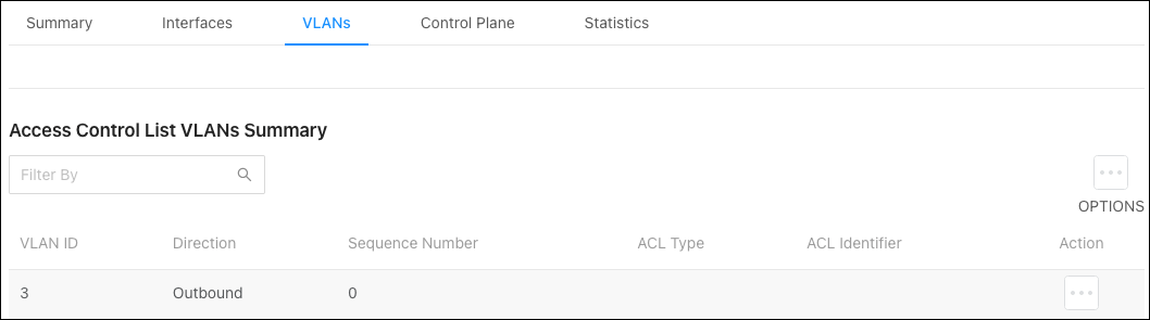
To Apply an ACL to a VLAN:
-
Click the Options (
) button, then Add. -
Select the VLAN ID or VLAN ID range to apply the ACL rule to.
-
Select a Direction for the packets to be checked against. If the packets should be checked against the ACL rules when the port(s) receives it, select Inbound. Select Outbound if the packets should be checked when the packets are exiting the port(s).
-
Enter a Sequence Number between 1 to 4294967295. Typing 0 auto-generates a sequence number. The order the ACL is applied to traffic on the interface relative to other ACLs associated with the interface in the same direction. When multiple ACLs are applied to the same interface in the same direction, the ACL with the lowest sequence number is applied first, and the other ACLs are applied in ascending numerical order.
-
Select the ACL Identifier of the ACL rule to apply to the port(s).
-
Click Add, then Apply at the top of the page.

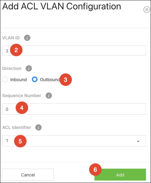
Control Plane
Use this page to assign Sequence Numbers to ACLs.
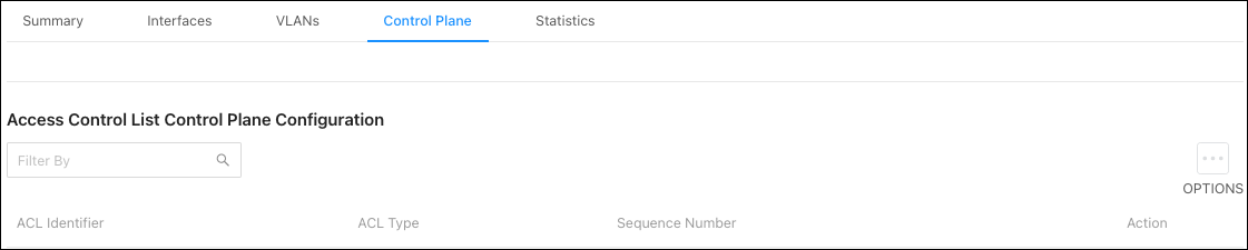
To assign a Sequence Number to an ACL:
-
Click Options (
), then Add to add open a new Contorl Plane window. -
Enter a Sequence Number between 1 and 4294967295 to indicate the position of the rule in the ACL. Type in 0 to auto-generate a sequence number.
-
Select an ACL Identifier to apply the Sequence Number to.
After a Control Plane has been added you can use the Action button to edit or delete an entry from the table.
Statistics
Use this page to view how many packets an ACL has forwarded or discarded until the number reaches the rollover value of the counter. ACL counters do not interact with DiffServ policies or policy-based routing counters.
To Clear the Counters:
-
Click the Options (
) button, then Clear. -
Select a Clear Counter Mode.
If Rule counter is selected, ACL Identifier and Sequence Number must be provided. If clear ACL counter is selected, the user can provide ACL Type to clear the hit count of all ACLs in that type or provide an ACL Identifier to clear the hit count of that ACL. -
Click OK.
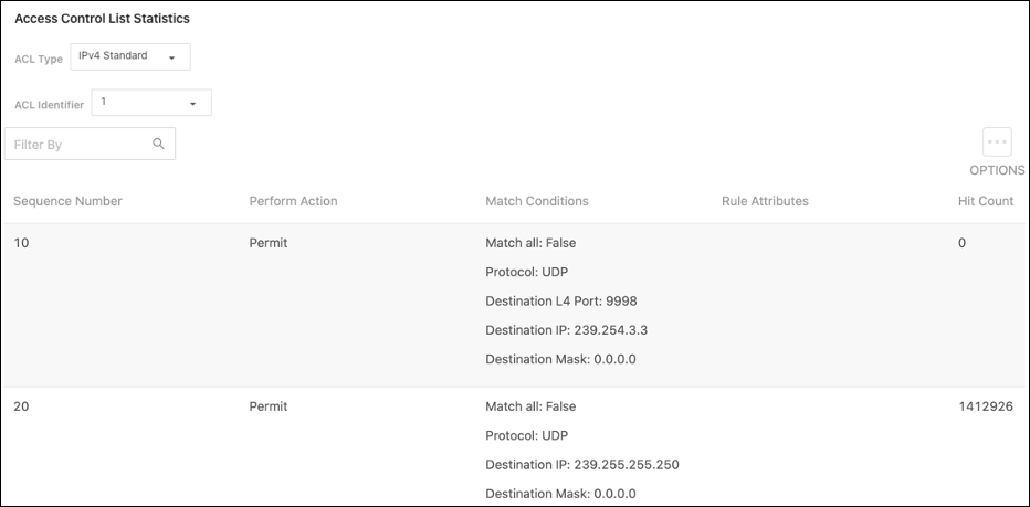
Table field descriptions:
-
Sequence Number — The number that indicates the rule position within the ACL.
-
Perform Action — Whether the rule permits or denies traffic.
-
Match Conditions — The criteria used to determine if the network traffic matches the ACL rule.
-
Rule Attributes — Each action the ACL rule performs.
-
Hit Count — The number of packets that match the ACL rule.
If a rule does not have a rate limit, the hit count is the number of matched packets the port forwarded or discarded.
If a rule has a rate limit, and the sent traffic exceeds the configured rate, the hit count displays the matched packet count equal to the sent rate.
If the sent traffic rate is less than the configured rate, the hit count displays only the matched packet count.
ACL Configuration
IPv4 Standard
Use this page to configure IPv4 Standard ACLs. Select an ACL Identifier from the dropdown, then click the Options () button to edit or Resequence multiple ACLs or the Actions button to edit a single ACL.
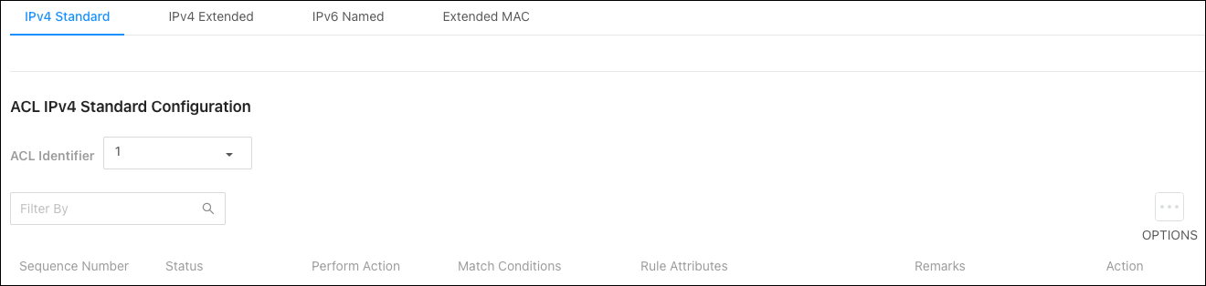
Configurable settings include:
-
Perform Action — The action to take when a packet or frame matches the criteria in the rule:
-
Permit — The packet or frame is forwarded.
-
Deny — The packet or frame is dropped.
-
-
Remark - Accepts alpha-numeric and special characters (-, _, and space) and is also case-sensitive. It can have 1 to 100 characters.
-
Every — When selected, all packets will match the rule and are either permitted or denied. This option is exclusive to all other match criteria and no other match criteria can be configured. To configure specific match criteria, do not enable Every.
-
Source IP Address — The source port IP address in the packet and source IP wildcard mask (in the next field) to compare to the IP address in a packet header.
-
Source Wildcard Mask — Wildcard masks determine which bits in the IP address are used and which are ignored. A wildcard mask of 255.255.255.255 indicates that no bit is important. A wildcard of 0.0.0.0 indicates that all the bits are important.
Wildcard masking for ACLs operates like the inverse of a subnet mask. With a subnet mask, the mask has ones (1's) in the bit positions used for the network address, and zeros (0's) for the bit positions that are not used. In contrast, a wildcard mask has (0's) in a bit position that must be checked. A '1' in a bit position of the ACL mask indicates the corresponding bit can be ignored. This field is required when you configure a source IP address.
-
Assign Queue — The number that identifies the hardware egress queue that will handle all packets that match this rule.
-
Interface — Select an interface (port) to associate with the rule.
-
Interface Action — Select one of the following options:
-
Redirect – Redirects traffic that meets the rule to the selected interface instead of being processed on the original port.
-
Mirror – Mirrors (copies) traffic that matches the rule to the selected interface.
-
-
Log — Enables logging for the ACL rule (subject to resource availability in the device). If the Access List Trap Flag is also enabled, periodic traps are generated indicating the number of times this rule went into effect during the current report interval. A fixed five-minute report interval is used for the entire system. A trap is not issued if the current interval’s ACL rule hit count is zero.
-
Time Range Name — The name of the time range that imposes a time limitation on the ACL rule, up to 31 characters. If a time range with the specified name does not exist, and the ACL containing this ACL rule is associated with an interface, the ACL rule is applied immediately. If a time range with the specified name exists, and the ACL containing this ACL rule is associated with an interface, the ACL rule is applied when the time range with the specified name becomes active. The ACL rule is removed when the time range with the specified name becomes inactive.
-
Committed Rate — The allowed transmission rate for packets on the interface.
-
Burst Size — The number of bytes allowed in a temporary traffic burst.
IPv4 Extended
Use this page to configure IPv4 Extended ACLs. Select an ACL Identifier from the dropdown, then click the Options ()button to edit or Resequence multiple ACLs or the Actions button to edit a single ACL.
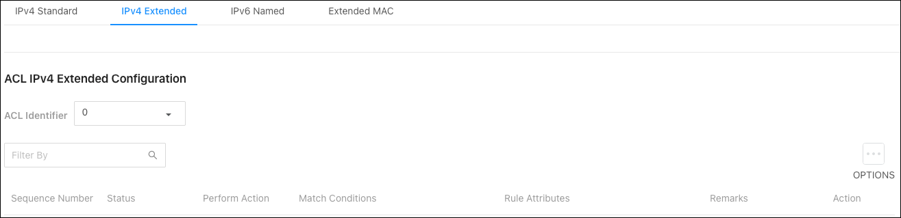
Configurable settings include:
-
Sequence — The position of a rule within the ACL. If the sequence number is not specified during rule creation, the rule is automatically assigned a sequence number after it is added to the ACL. The rules are displayed based on their position within the ACL, which can be renumbered. Packets are checked against the rule criteria in order, from the lowest-numbered rule to the highest. When the packet matches the criteria in a rule, it is handled according to the rule action and attributes. If no rule matches a packet, the packet is discarded based on the implicit deny all rule, which is the final rule in every ACL.
-
Perform Action — The action to take when a packet or frame matches the criteria in the rule:
-
Permit — The packet or frame is forwarded.
-
Deny — The packet or frame is dropped.
-
-
Remark - Accepts alpha-numeric and special characters (-, _, and space) and is also case-sensitive. It can have 1 to 100 characters.
-
Every — When selected, all packets will match the rule and are either permitted or denied. This option is exclusive to all other match criteria and no other match criteria can be configured. To configure specific match criteria, do not enable Every.
-
Protocol - The IANA-assigned protocol to match within the IP packet.
-
Fragments — IP ACL rule to match on fragmented IP packets.
-
Source IP Address — The source port IP address in the packet and source IP wildcard mask (in the next field) to compare to the IP address in a packet header.
-
Source Wildcard Mask — Wildcard masks determine which bits in the IP address are used and which are ignored. A wildcard mask of 255.255.255.255 indicates that no bit is important. A wildcard of 0.0.0.0 indicates that all the bits are important.
Wildcard masking for ACLs operates like the inverse of a subnet mask. With a subnet mask, the mask has ones (1's) in the bit positions used for the network address, and zeros (0's) for the bit positions that are not used. In contrast, a wildcard mask has (0's) in a bit position that must be checked. A '1' in a bit position of the ACL mask indicates the corresponding bit can be ignored. This field is required when you configure a source IP address.
-
Source L4 Port Option — The TCP/UDP source port to match in the packet header. Select Equal, Not Equal, Less Than, Greater Than, or Range and specify the port number or keyword in Source L4 Port Value.
-
Source L4 Port Value — TCP port keywords include BGP, Domain, Echo, FTP, FTP Data, HTTP, SMTP, Telnet, POP2, and POP3. UDP port keywords include Domain, Echo, NTP, RIP, SNMP, TFTP, TIME, and WHO. If it is not a keyword, it must be a string between 0 and 65535.
-
Source L4 Port Range Upper Bound — TCP port keywords include BGP, Domain, Echo, FTP, FTP Data, HTTP, SMTP, Telnet, POP2, and POP3. UDP port keywords include Domain, Echo, NTP, RIP, SNMP, TFTP, TIME, and WHO. If it is not a keyword, it must be a string between 0 and 65535.
-
Destination IP Address — The destination port IP address in the packet and destination IP wildcard mask (in the next field) to compare to the IP address in a packet header.
-
Destination Wildcard Mask — Wildcard masks determine which bits in the IP address are used and which are ignored. A wildcard mask of 255.255.255.255 indicates that no bit is important. A wildcard of 0.0.0.0 indicates that all the bits are important.
Wildcard masking for ACLs operates like the inverse of a subnet mask. With a subnet mask, the mask has ones (1's) in the bit positions used for the network address, and zeros (0's) for the bit positions that are not used. In contrast, a wildcard mask has (0's) in a bit position that must be checked. A '1' in a bit position of the ACL mask indicates the corresponding bit can be ignored. This field is required when you configure a source IP address.
-
Destination L4 Port Option — The TCP/UDP destination port to match in the packet header. Select Equal, Not Equal, Less Than, Greater Than, or Range and specify the port number or keyword in Source L4 Port Value.
-
Destination L4 Port Value — TCP port keywords include BGP, Domain, Echo, FTP, FTP Data, HTTP, SMTP, Telnet, POP2, and POP3. UDP port keywords include Domain, Echo, NTP, RIP, SNMP, TFTP, TIME, and WHO. If it is not a keyword, it must be a string between 0 and 65535.
-
DestinationL4 Port Range Upper Bound — TCP port keywords include BGP, Domain, Echo, FTP, FTP Data, HTTP, SMTP, Telnet, POP2, and POP3. UDP port keywords include Domain, Echo, NTP, RIP, SNMP, TFTP, TIME, and WHO. If it is not a keyword, it must be a string between 0 and 65535.
-
TTL Field Value — IP ACL rule to match on the specified TTL field value.
-
IGMP Type — The IP ACL rule to match on the specified IGMP type. This option is available only if the protocol is IGMP.
-
ICMP Type — The IP ACL rule to match on the specified ICMP type. This option is available only if the protocol is ICMP.
-
ICMP Code — The IP ACL rule to match on the specified ICMP code. This option is available only if the protocol is ICMP.
-
ICMP Message — IP ACL rule to match on the ICMP message type and code. Select one of the following supported ICMP messages: Echo, Echo-Reply, Host-Redirect, Mobile-Redirect, Net-Redirect, Net-Unreachable, Redirect, Packet-Too-Big, Port-Unreachable, Source-Quench, Router-Solicitation, Router-Advertisement, Time-Exceeded, TTL-Exceeded, and Unreachable. This option is available only if the protocol is ICMP.
-
TCP Flags — The IP ACL rule to match on the TCP flags. When a + flag is specified, a match occurs if the flag is set in the TCP header. When a - flag is specified, a match occurs if the flag is not set in the TCP header. When Established is specified, a match occurs if either RST or ACK bits are set in the TCP header. This option is available only if the protocol is TCP.
-
IP DSCP — Matches the packet IP DiffServ Code Point (DSCP) value to the rule. The DSCP value is defined as the high-order six bits of the Service Type octet in the IP header. This field can be a keyword or a string between 0 - 63.
-
IP Precedence — Matches the IP Precedence value to the rule. The IP Precedence field in a packet is defined as the high-order three bits of the Service Type octet in the IP header.
-
IP TOS Bits — Matches on the Type of Service (TOS) bits in the IP header. The IP TOS field in a packet is defined as all eight bits of the Service Type octet in the IP header. For example, to check for an IP TOS value having bits 7 and 5 set and bit 1 clear, where bit 7 is most significant, use a TOS Bits value of 0xA0 and a TOS Mask of 0xFF. Requires the bits in a packet's TOS field to match the two-digit hexadecimal number entered in this field.
-
IP TOS Wildcard Mask — The bit positions that are used for comparison against the IP TOS field in a packet. Specifying TOS Mask is optional. The format would be the same as IP TOS Bits: two-digit hexadecimal numbers.
-
Assign Queue — The number that identifies the hardware egress queue that will handle all packets matching this rule.
-
Interface — Select an interface (port) to associate with the rule.
-
Interface Action — Select one of the following options:
-
Redirect – Redirects traffic that meets the rule to the selected interface instead of being processed on the original port.
-
Mirror – Mirrors (copies) traffic that matches the rule to the selected interface.
-
-
Log — Enables logging for the ACL rule (subject to resource availability in the device). If the Access List Trap Flag is also enabled, periodic traps are generated indicating the number of times this rule went into effect during the current report interval. A fixed five-minute report interval is used for the entire system. A trap is not issued if the current interval’s ACL rule hit count is zero.
-
Time Range Name — The name of the time range that imposes a time limitation on the ACL rule, up to 31 characters. If a time range with the specified name does not exist, and the ACL containing this ACL rule is associated with an interface, the ACL rule is applied immediately. If a time range with the specified name exists, and the ACL containing this ACL rule is associated with an interface, the ACL rule is applied when the time range with the specified name becomes active. The ACL rule is removed when the time range with the specified name becomes inactive.
-
Committed Rate — The allowed transmission rate for packets on the interface.
-
Burst Size — The number of bytes allowed in a temporary traffic burst.
IPv6 Named
Use this page to configure IPv6 Extended ACLs. Select an ACL Identifier from the dropdown, then click the Options () button to edit or Resequence multiple ACLs or the Actions button to edit a single ACL.
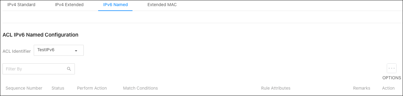
Configurable options include:
-
Sequence — The position of a rule within the ACL. If the sequence number is not specified during rule creation, the rule is automatically assigned a sequence number after it is added to the ACL. The rules are displayed based on their position within the ACL, which can be renumbered. Packets are checked against the rule criteria in order, from the lowest-numbered rule to the highest. When the packet matches the criteria in a rule, it is handled according to the rule action and attributes. If no rule matches a packet, the packet is discarded based on the implicit deny all rule, which is the final rule in every ACL.
-
Perform Action — The action to take when a packet or frame matches the criteria in the rule:
-
Permit — The packet or frame is forwarded.
-
Deny — The packet or frame is dropped.
-
-
Remark - Accepts alpha-numeric and special characters (-, _, and space) and is also case-sensitive. It can have 1 to 100 characters.
-
Every — When selected, all packets will match the rule and are either permitted or denied. This option is exclusive to all other match criteria and no other match criteria can be configured. To configure specific match criteria, do not enable Every.
-
Protocol - Enter the IANA-assigned protocol to match within the IP packet.
-
Fragments — IP ACL rule to match on fragmented IP packets.
-
Source Prefix — The IPv6 prefix combined with IPv6 prefix length of the network or host from which the packet is being sent.
-
Source Prefix Length — To indicate a destination host, specify an IPv6 prefix length of 128.
-
Source L4 Port Option — The TCP/UDP destination port to match in the packet header. Select Equal, Not Equal, Less Than, Greater Than, or Range and specify the port number or keyword in Source L4 Port Value.
-
Source L4 Port Value — TCP port keywords include BGP, Domain, Echo, FTP, FTP Data, HTTP, SMTP, Telnet, POP2, and POP3. UDP port keywords include Domain, Echo, NTP, RIP, SNMP, TFTP, TIME, and WHO. If it is not a keyword, it must be a string between 0 and 65535.
-
Source L4 Port Range Upper Bound — TCP port keywords include BGP, Domain, Echo, FTP, FTP Data, HTTP, SMTP, Telnet, POP2, and POP3. UDP port keywords include Domain, Echo, NTP, RIP, SNMP, TFTP, TIME, and WHO. If it is not a keyword, it must be a string between 0 and 65535.
-
Destination Prefix — The IPv6 prefix combined with the IPv6 prefix length to compare to a packet's destination IPv6 address as a match criteria for the IPv6 ACL rule.
-
Destination Prefix Length — To indicate a destination host, specify an IPv6 prefix length of 128.
-
Destination L4 Port Option — The TCP/UDP destination port to match in the packet header. Select Equal, Not Equal, Less Than, Greater Than, or Range and specify the port number or keyword in Source L4 Port Value.
-
Destination L4 Port Value — TCP port keywords include BGP, Domain, Echo, FTP, FTP Data, HTTP, SMTP, Telnet, POP2, and POP3. UDP port keywords include Domain, Echo, NTP, RIP, SNMP, TFTP, TIME, and WHO. If it is not a keyword, it must be a string between 0 and 65535.
-
DestinationL4 Port Range Upper Bound — TCP port keywords include BGP, Domain, Echo, FTP, FTP Data, HTTP, SMTP, Telnet, POP2, and POP3. UDP port keywords include Domain, Echo, NTP, RIP, SNMP, TFTP, TIME, and WHO. If it is not a keyword, it must be a string between 0 and 65535.
-
TTL Field Value —IP ACL rule to match on the specified TTL field value.
-
ICMP Type — The IP ACL rule to match on the specified ICMP type. This option is available only if the protocol is ICMP.
-
ICMP Code — The IP ACL rule to match on the specified ICMP code. This option is available only if the protocol is ICMP.
-
ICMP Message — IP ACL rule to match on the ICMP message type and code. Select one of the following supported ICMP messages: Echo, Echo-Reply, Host-Redirect, Mobile-Redirect, Net-Redirect, Net-Unreachable, Redirect, Packet-Too-Big, Port-Unreachable, Source-Quench, Router-Solicitation, Router-Advertisement, Time-Exceeded, TTL-Exceeded, and Unreachable. This option is available only if the protocol is ICMP.
-
TCP Flags — The IP ACL rule to match on the TCP flags. When a + flag is specified, a match occurs if the flag is set in the TCP header. When a - flag is specified, a match occurs if the flag is not set in the TCP header. When Established is specified, a match occurs if either RST or ACK bits are set in the TCP header. This option is available only if the protocol is TCP.
-
Flow Label — A 20-bit number that is unique to an IPv6 packet, used by end stations to signify quality-of-service handling in routers. This value must be between 0 - 1048575.
-
IP DSCP — Matches the packet IP DiffServ Code Point (DSCP) value to the rule. The DSCP value is defined as the high-order six bits of the Service Type octet in the IP header. This field can be a keyword or a string between 0 - 63.
-
Routing — IPv6 ACL rule to match on routed packets.
-
Assign Queue — The number that identifies the hardware egress queue that will handle all packets matching this rule.
-
Interface — Select an interface (port) to associate with the rule.
-
Interface Action — Select one of the following options:
-
Redirect — Redirects traffic that meets the rule to the selected interface instead of being processed on the original port.
-
Mirror — Mirrors (copies) traffic that matches the rule to the selected interface.
-
-
Log — Enables logging for the ACL rule (subject to resource availability in the device). If the Access List Trap Flag is also enabled, periodic traps are generated indicating the number of times this rule went into effect during the current report interval. A fixed five-minute report interval is used for the entire system. A trap is not issued if the current interval’s ACL rule hit count is zero.
-
Time Range Name — The name of the time range that imposes a time limitation on the ACL rule, up to 31 characters. If a time range with the specified name does not exist, and the ACL containing this ACL rule is associated with an interface, the ACL rule is applied immediately. If a time range with the specified name exists, and the ACL containing this ACL rule is associated with an interface, the ACL rule is applied when the time range with the specified name becomes active. The ACL rule is removed when the time range with the specified name becomes inactive.
-
Committed Rate — The allowed transmission rate for packets on the interface.
-
Burst Size — The number of bytes allowed in a temporary traffic burst.
Extended MAC
Use this page to configure MACExtended ACLs. Select an ACL Identifier from the dropdown, then click the Options () button to edit or Resequence multiple ACLs or the Actions button to edit a single ACL.
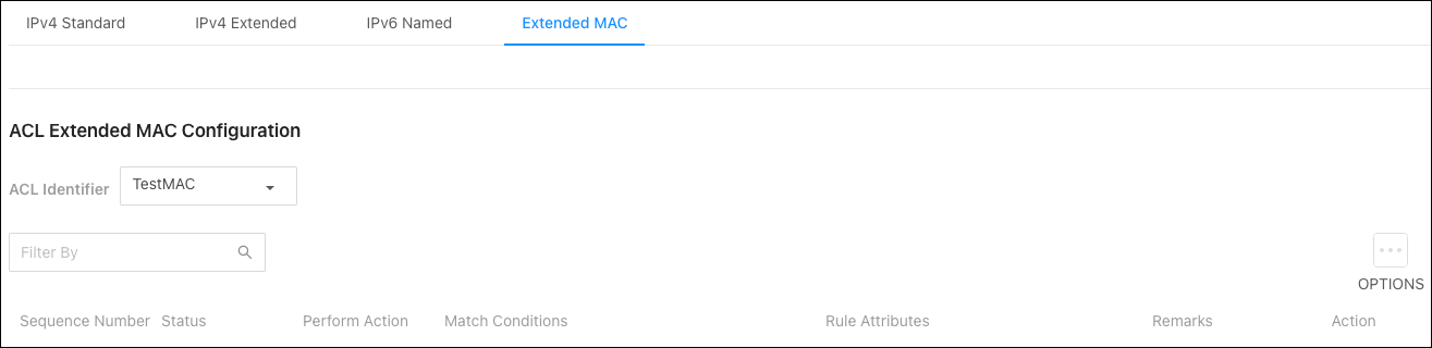
Configurable options include:
-
Sequence Number — The position of a rule within the ACL. If the sequence number is not specified during rule creation, the rule is automatically assigned a sequence number after it is added to the ACL. The rules are displayed based on their position within the ACL, which can be renumbered. Packets are checked against the rule criteria in order, from the lowest-numbered rule to the highest. When the packet matches the criteria in a rule, it is handled according to the rule action and attributes. If no rule matches a packet, the packet is discarded based on the implicit deny all rule, which is the final rule in every ACL.
-
Perform Action — The action to take when a packet or frame matches the criteria in the rule:
-
Permit — The packet or frame is forwarded.
-
Deny — The packet or frame is dropped.
-
-
Remark - Accepts alpha-numeric and special characters (-, _, and space) and is also case-sensitive. It can have 1 to 100 characters.
-
Every — When selected, all packets will match the rule and are either permitted or denied. This option is exclusive to all other match criteria and no other match criteria can be configured. To configure specific match criteria, do not enable Every.
-
Class of Service — The 802.1p user priority value to match within the Ethernet frame.
-
EtherType — The EtherType value to match in an Ethernet frame. Specify the number associated with the EtherType or specify one of the following keywords: appletalk, arp, ibmsna, ipv4, ipv6, IPX, mplsmcast, mplsucast, netbios, novell, pppoe, or rarp.
-
Source MAC Address — The MAC address to match to an Ethernet frame's source port MAC address. If desired, enter the MAC Mask associated with the source MAC to match.
-
Source MAC Mask — The MAC address mask specifies which bits in the source MAC to compare against an Ethernet frame. Use F's and zeros in the MAC mask, which is in a wildcard format. An F means that the bit is not checked, and a zero in a bit position means that the data must equal the value given for that bit. For example, if the MAC address is aa:bb:cc:dd:ee:ff, and the mask is 00:00:ff:ff:ff:ff, all MAC addresses with aa:bb:xx:xx:xx:xx result in a match (where x is any hexadecimal number).
-
Destination MAC Address — The MAC address to match to an Ethernet frame's destination port MAC address. If desired, enter the MAC Mask associated with the destination MAC to match.
-
Destination MAC Mask — The MAC address mask specifies which bits in the destination MAC to compare against an Ethernet frame. Use F's and zeros in the MAC mask, which is in a wildcard format. An F means that the bit is not checked, and a zero in a bit position means that the data must equal the value given for that bit. For example, if the MAC address is aa:bb:cc:dd:ee:ff, and the mask is 00:00:ff:ff:ff:ff, all MAC addresses with aa:bb:xx:xx:xx:xx result in a match (where x is any hexadecimal number).
-
VLAN — The VLAN ID to match within the Ethernet frame.
-
Secondary VLAN — The secondary VLAN ID to match within the Ethernet frame.
-
Assign Queue — The number that identifies the hardware egress queue that will handle all packets matching this rule.
-
Interface — Select an interface (port) to associate with the rule.
-
Interface Action — Select one of the following options:
-
Redirect — Redirects traffic that meets the rule to the selected interface instead of being processed on the original port.
-
Mirror — Mirrors (copies) traffic that matches the rule to the selected interface.
-
-
Log — Enables logging for the ACL rule (subject to resource availability in the device). If the Access List Trap Flag is also enabled, periodic traps are generated indicating the number of times this rule went into effect during the current report interval. A fixed five-minute report interval is used for the entire system. A trap is not issued if the current interval’s ACL rule hit count is zero.
-
Time Range Name — The name of the time range that imposes a time limitation on the ACL rule, up to 31 characters. If a time range with the specified name does not exist, and the ACL containing this ACL rule is associated with an interface, the ACL rule is applied immediately. If a time range with the specified name exists, and the ACL containing this ACL rule is associated with an interface, the ACL rule is applied when the time range with the specified name becomes active. The ACL rule is removed when the time range with the specified name becomes inactive.
-
Committed Rate — The allowed transmission rate for packets on the interface.
-
Burst Size — The number of bytes allowed in a temporary traffic burst.
DIffserv
DiffServ (Differentiated Services) allows traffic to be classified into streams and given QoS treatment with defined per-hop behaviors. Packets are classified and processed by specified criteria that’s defined by a class.
Policy attributes may be defined on a per-class instance basis and are applied when a match occurs. A policy can contain multiples classes. When the policy is active, the actions taken depend on which class matches the packet.
Global
Use this page to enable DiffServ and view the MIB table.
Note: If disabled, the DiffServ configuration is retained and can be changed.
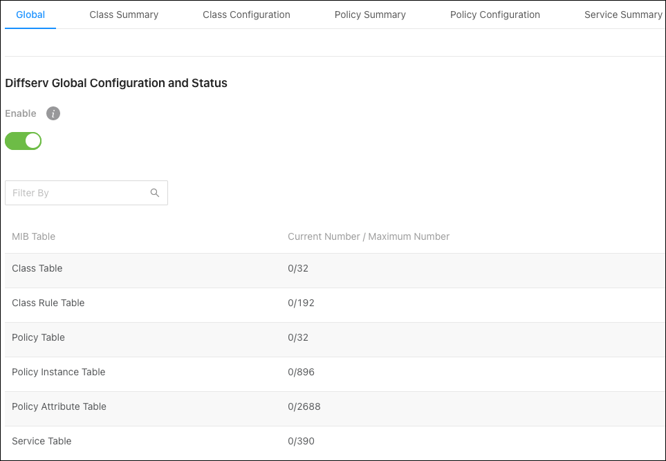
Class Summary
Use this page to create or remove DiffServ classes and to view a summary of each class on the switch. The Action () button can be used to Edit or Delete an existing class.
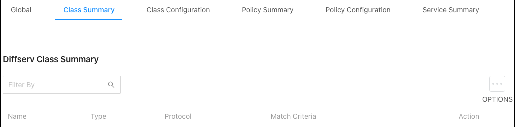
To Add a DiffServ Class:
-
Click the Options (
) button , then Add. -
Specify a Class Type:
-
All: All the DiffServ Class criteria must be met for a packet match.
-
Any: If any of the DiffServ Class criteria are met there is a packet match.
-
Select the layer 3 Protocol to use for filtering class types, which is either IPv4, IPv6, or you can select None.
-
Click Add to close the window, then click Apply at the top of the page.

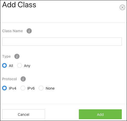
Class Configuration
Use this page to add Match Criteria to a DiffServ class.
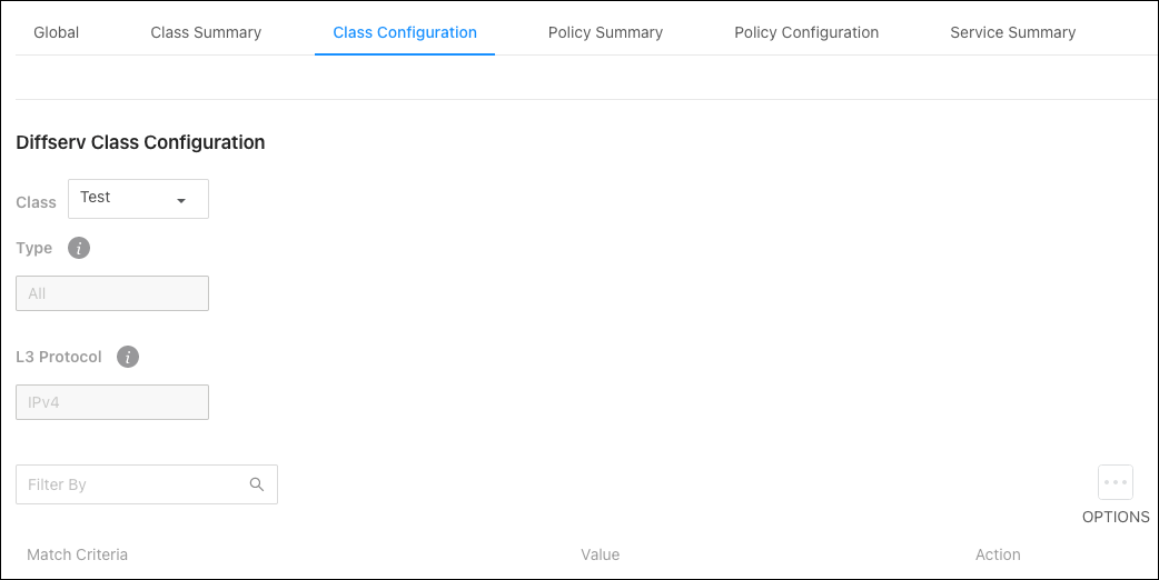
To add Match Criteria to a DiffServ Class, use the Class dropdown to select a previously created class, then click the Options () button, then Add, for the Add Match Criteria window to appear.
Configurable options include:
-
Any — Enable for all packets to be considered to match the specified class. Configuring additional match criteria is unnecessary if Any is selected because a match will occur on all packets.
-
Reference ACL — Use the dropdown to select a previously configured ACL to match the criteria to.
-
Reference Class — Select this option to reference a class for match criteria. A class can reference at most one other class of the same type.
-
Class of Service — This option requires the Class of Service (CoS) value in an Ethernet frame header to match the specified CoS value.
-
Secondary Class of Service — Select a secondary CoS value in an Ethernet frame header to match.
-
EtherType Keyword — Use the dropdown to select a common protocol to require the EtherType value in the Ethernet frame header to match.
-
EtherType Value — This field accepts custom EtherType values.
-
VLAN ID — Enter a VLAN ID to require a packet's VLAN ID to match or a VLAN ID within a continuous range. If you configure a range, a match occurs if a packet's VLAN ID is the same as any VLAN ID within the range.
-
Secondary VLAN ID — Enter a secondary VLAN ID to match or a secondary VLAN ID within a continuous range. If you configure a range, a match occurs if a packet's secondary VLAN ID is the same as any secondary VLAN ID within the range.
-
Source MAC Address — Enter a MAC address to require a packet's source MAC address to match.
-
Source MAC Mask — The MAC address mask specifies which bits in the destination MAC to compare against an Ethernet frame. Use F's and zeros in the MAC mask, which is in a wildcard format. An F means that the bit is not checked, and a zero in a bit position means that the data must equal the value given for that bit. For example, if the MAC address is aa:bb:cc:dd:ee:ff, and the mask is 00:00:ff:ff:ff:ff, all MAC addresses with aa:bb:xx:xx:xx:xx result in a match (where x is any hexadecimal number).
Note: This is not a wildcard mask like ACLs use.
-
Destination MAC Address — Enter a MAC address to require a packet's destination MAC address to match.
-
Destination MAC Mask — The MAC address mask specifies which bits in the destination MAC to compare against an Ethernet frame. Use F's and zeros in the MAC mask, which is in a wildcard format. An F means that the bit is not checked, and a zero in a bit position means that the data must equal the value given for that bit. For example, if the MAC address is aa:bb:cc:dd:ee:ff, and the mask is 00:00:ff:ff:ff:ff, all MAC addresses with aa:bb:xx:xx:xx:xx result in a match (where x is any hexadecimal number).
Note: This is not a wildcard mask like ACLs use.
-
Source IP Address — The source port IP address in the packet and source IP to compare to the IP address in a packet header.
-
Source IP Mask — A valid subnet mask, which determines the bits in the IP address that are significant.
Note: This is not a wildcard mask like ACLs use.
-
Destination IP Address — The destination port IP address in the packet and destination IP to compare to the IP address in a packet header.
-
Destination IP Mask — A valid subnet mask, which determines the bits in the IP address that are significant.
Note: This is not a wildcard mask like ACLs use.
-
IP Precedence — Use the dropdown to select a packet's IP Precedence value to match. The IP Precedence field in a packet is defined as the high-order three bits of the Service Type octet in the IP header.
-
IP Type of Service Bits — Enter a two-digit hexadecimal number to match the bits in a packet's ToS field. The IP ToS field in a packet is defined as all eight bits of the Service Type octet in the IP header.
-
IP Type of Service Mask — Specify the bit positions that are used for comparison against the IP ToS field in a packet.
-
Protocol — Use the dropdown to select an L4 keyword to require a packet header's Layer 4 protocol to match the specified value. If you select a keyword you cannot configure a Protocol Value.
-
Protocol Value — Enter the IANA L4 protocol number value to match.
-
Source L4 Protocol — Use the dropdown to select the desired L4 keyword from the list on which the match is based. If you select a keyword, you cannot enter a Source L4 Port value.
-
Source L4 Port — Enter a source port, or port range, to add to the criteria. If you configure a range, a match occurs if a packet's source port number is the same as any destination port number within the range.
-
Destination L4 Protocol — Select an L4 keyword from the list to add to the criteria. If you select a keyword, you cannot enter a Destination L4 Port value.
-
Destination L4 Port — Enter a destination port, or port range, to add to the criteria. If you configure a range, a match occurs if a packet's destination port number is the same as any destination port number within the range.
-
IP DSCP Keyword — Select a IP DSCP keyword code to add to the criteria. If you select a keyword, you cannot configure an IP DSCP Value.
Note: be and cs0 are identical.
-
IP DSCP Value — Enter an IP DSCP Value to add to the criteria.
Policy Summary
Use this page to create or remove DiffServ policies. The table summarizes information about the policies configured on the switch.
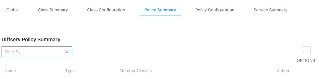
To add a Policy:
-
Click the Options (
) button, then Add. -
Enter a Policy Name.
-
The Type field has one option to enable. Select In, to apply the policy to inbound traffic, or Out to apply it to outbound traffic. Click Add when finished.
Policy Configuration
Use this page to configure policy attributes. The policy attributes identify the action or actions taken when a packet matches a class rule.
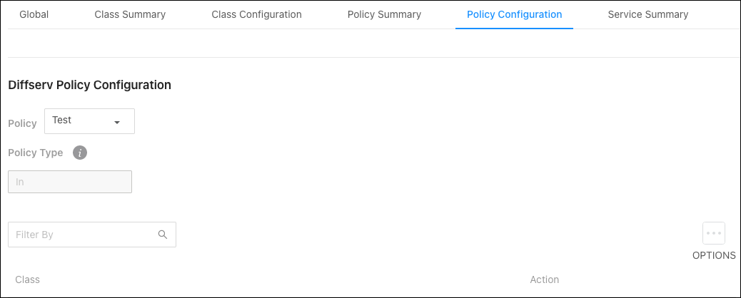
To add Policy Attributes, use the Policy dropdown to select a previously created policy, then click the Options () button, then Add, for the Add Policy Attribute window to appear.
Configurable options include:
-
Class — The DiffServ class associated with the policy. The policy is applied to a packet when a class match within that policy-class is found.
-
Assign Queue — Select a Queue ID Value to which the packets of this policy-class are assigned.
-
Drop — Enable to drop packets that match the policy class.
-
Mark Class of Service — Use this field to mark all packets in a traffic stream with the specified Class of Service (CoS) queue value. Enter a value (0 to 7) to mark in the priority field of the 802.1p header (the only tag in a single tagged packet or the first or outer 802.1Q tag of a double VLAN tagged packet). If the packet does not already contain this header, one is inserted.
-
Mark CoS as secondary CoS — Enable to mark the priority field of the 802.1p header in the outer tag of a double-VLAN tagged packet with the same CoS value that is included in the inner tag. Determine whether to support mark COS as secondary COS according to the chip.
-
Mark IP DSCP — Enter a value (1 through 7) to mark packets in the policy’s associated traffic stream.
-
Mark IP Precedence — Enter a value (1 through 7) to mark packets in a traffic stream that matches the policy. The Mark IP Precedence field is then selectable in other fields.
-
Mirror Interface — Use the dropdown to select a specified egress port (physical or LAG) to copy the traffic stream to without bypassing normal packet forwarding. This action can occur in addition to any marking or policing action. It may also be specified along with a QoS queue assignment. Use the dropdown to select the interface to mirror traffic to.
-
Police Simple Color Mode — Select this option to enable simple traffic policing. Simple policing uses a single data rate and burst size, resulting in either a conform or violate action.
-
Police Simple Committed Rate (Kbps) — Enter the maximum arrival rate of incoming packets for the policy, in Kbps.
-
Police Simple Committed Burst Size (Kbytes) — Enter the maximum amount of conforming traffic allowed in a burst.
-
Police Simple Conform Action — Select the action to take on packets below the committed rate conforms.
-
Police Simple Violate Action — Select the action to take on packets above the committed rate violates.
-
Police Single Rate Color Mode — Select an option to enable single-rate traffic policing. Single-rate policing uses a single data rate and two burst sizes, resulting in a conform, violate, or exceed action.
-
Police Single Rate Committed Rate (Kbps) — Enter the maximum arrival rate of incoming packets for the policy, in Kbps.
-
Police Single Rate Committed Burst Size (Kbytes) — Enter the amount of packets allowed in a burst when the arrival rate is under conforms to the Single Rate Committed Rate value.
-
Police Single Rate Excess Burst Size (Kbytes) — Enter the amount of conforming traffic allowed to accumulate beyond the Committed Burst Size (Kbytes) value during long idle times. This value allows for occasional bursting.
-
Police Single Rate Conform Action — Select the action to take on packets below the committed rate conforms.
-
Police Single Rate Exceed Action — Select the action to take when a burst of packets exceeds the Police Single Rate Committed Burst Rate.
-
Police Single Rate Violate Action — Select the action to take on packets above the committed rate violates.
-
Police Two Rate Color Mode — Select an option to enable simple traffic policing. Two-rate policing uses two data rates and burst sizes, resulting in either a conform, violate, or exceed action.
-
Police Two Rate Committed Rate (Kbps) — Enter the maximum arrival rate of incoming packets for the policy, in Kbps.
-
Police Two Rate Committed Burst Size (Kbytes) — Enter the amount of packets allowed in a burst when the arrival rate is under conforms to the Two Rate Committed Rate value.
-
Police Two Rate Peak Rate (Kbps) — Enter the maximum (peak) information rate for the arrival of incoming packets for this class.
-
Police Two Rate Excess Burst Size (Kbytes) — Enter the amount of conforming traffic allowed to accumulate beyond the Committed Burst Size (Kbytes) value during long idle times. This value allows for occasional bursting.
-
Police Two Rate Conform Action — Select the action to take on packets below the committed rate conforms.
-
Police Two Rate Exceed Action — Select the action to take when a burst of packets exceeds the Police Two Rate Committed Burst Rate.
-
Police Two Rate Violate Action — Select the action to take on packets above the committed rate violates.
-
Redirect Interface — Select an interface (switchport or LAG) to force a classified traffic stream to.
Service Summary
Use this page to add or remove DiffServ policies to interfaces or edit the policy mappings, by clicking the Options () button.
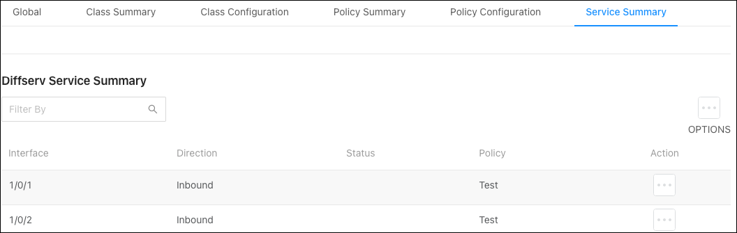
VoIP
Voice over Internet Protocol (VoIP) allows telephone calls over a data network, like the internet. With the network acting as the backbone for many multimedia applications, it’s important to properly configure the switch to prioritize VoIP traffic to make sure the application runs smoothly.
The Auto VoIP feature detects VoIP streams in the switch and provides them a better class of service. Interfaces with Auto VoIP configuration scan incoming traffic for the following protocols:
-
Session Initiation Protocol (SIP)
-
H.323
-
Skinny Client Control Protocol (SCCP)
When the switch detects a call-control protocol it assigns that session’s traffic to the highest CoS queue, generally used for time-sensitive traffic.
Global
Use this page to assign a VLAN to segregate the VoIP traffic from non-VoIP traffic. This feature does not rely on LLDP-MED support from the connected devices.
Enter the VLAN ID to assign the VoIP traffic to.
OUI Table
Use this page to add Organizationally Unique Identifiers (OUIs) that a connected device may have in their OUI database. Device manufacturers can include OUIs in a network adapter to help identify it. OUI’s are a unique 24-bit number assigned by the IEEE registration authority. The switch comes with some preconfigured OUIs.
To add an OUI to the table, click the Options () button. To remove an OUI, click the Action button next to its entry.
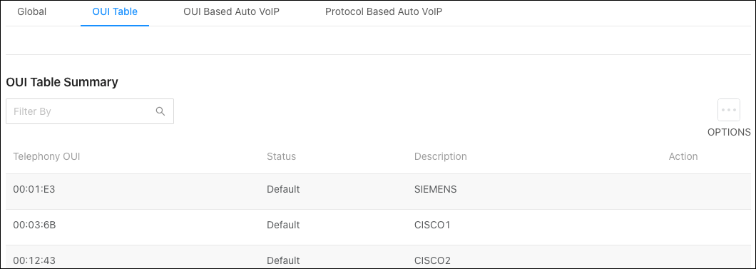
OUI Based Auto VoIP
Use this page to enter a Priority value for traffic that matches a configured OUI.
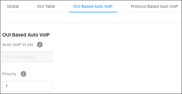
The OUI Table allows you to enable Auto VoIP on interfaces and view their operational status.
OUI-based Auto VoIP can be enabled on an interface by:
-
Clicking the toggles next to an interface.
-
Clicking the Action (
) button on the far right of the interface row, or the Options button above the table to select multiple interfaces.
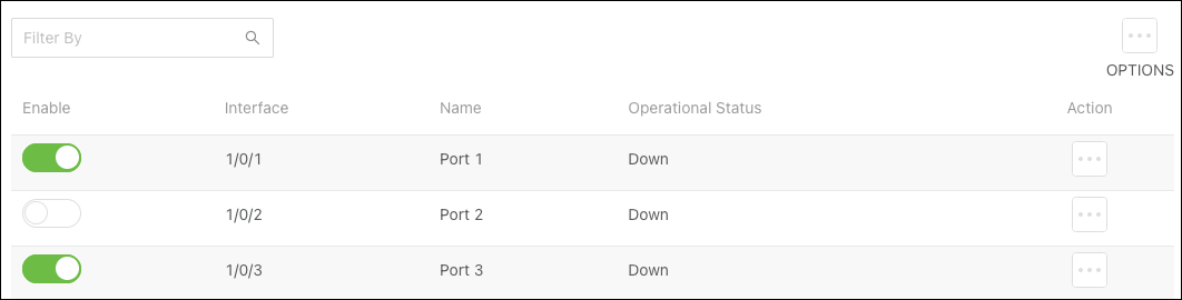
No matter how you select an interface, click the Apply button at the top of the page to confirm the selection.
Protocol Based Auto VoIP
Use this page to configure protocol-based Auto VoIP settings and to enable or disable Auto VoIP on an interface.
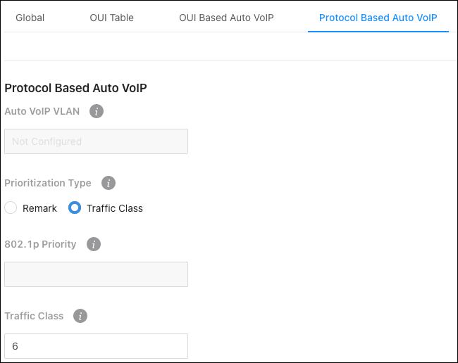
Select a Prioritization Type for VoIP traffic when a call-control protocol is detected. Options are:
-
Remark — Remark the voice traffic with the specified 802.1p priority value at the ingress interface.
-
Traffic Class — Assign VoIP traffic to the specified traffic class when egressing the interface.
Protocol-based Auto VoIP can be enabled on an interface by:
-
Clicking the toggles next to an interface.
-
Clicking the Action (
) button on the far right of the interface row, or the Options button above the table to select multiple interfaces.
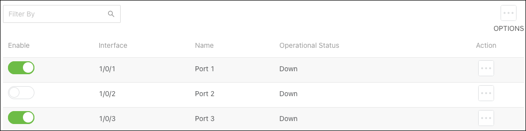
802.1p
The priority mapping feature allows traffic prioritization at the MAC level by using the 802.1p tag attached to the layer 2 frame. Each switch port has multiple queues to give preference to distinct packets based on the class of service (CoS) criteria specified. The rate at which a packet is sent to a port depends on how the queue is configured and the amount of traffic in other queues for the port. If there must be a delay, packets are held in the queue until the scheduler authorizes the transmission.
Use the Options () button to edit the priority values for multiple ports, or the Action button to edit an individual port.
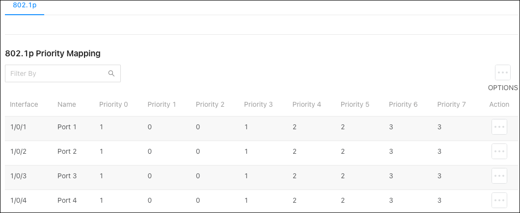
Table field descriptions:
-
Interface — The user-configured name of the port or link aggregation group (LAG).
-
Priority — The heading row of the table that lists the 802.1p priority level (0-7). Incoming frames with an assigned 802.1p priority value are mapped to the corresponding traffic class in the device.
-
Traffic Class — Traffic class is the data displayed in the table, which Is the internal traffic class corresponding to the 8021.p priority level.
Voice VLAN
Enable Voice VLAN on interfaces that carry voice traffic to ensure that the sound quality of an IP phone does not deteriorate when there is high data traffic on the interface.
Configuration
Use this page to Enable the Voice VLAN feature globally.
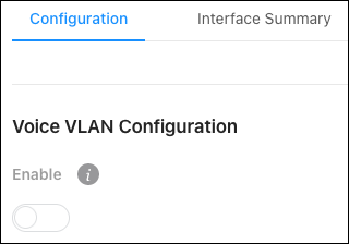
Interface Summary
Use this page to configure Voice VLAN features per interface by clicking the Action () button on the interface row. Click the Options button to refresh the page.
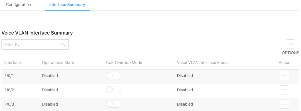
Configurable options include:
-
CoS Override Mode — When enabled, the port ignores the 802.1p priority value in the Ethernet frames it receives from connected devices.
-
Voice VLAN Interface Mode — Use the dropdown to select how an IP phone connected to the interface should send the voice traffic. Options are:
-
VLAN ID — Forward voice traffic in the specified voice VLAN.
-
Dot1p — Tag voice traffic with the specified 802.1p priority value.
-
None — Use the settings configured on the IP phone to send untagged voice traffic.
-
Untagged — Send untagged voice traffic.
-
Disable — Disables the Voice VLAN feature on the interface.
-